Electrical socket contact for high current applications

a socket contact and high current technology, applied in the direction of coupling device connection, coupling contact member, electrical apparatus, etc., can solve the problem of not being able to make contact with the socket contact from this side of the housing, and achieve the effect of preventing plugging and greater toleran

Active Publication Date: 2007-03-22
KOSTAL KONTAKT SYST
View PDF7 Cites 35 Cited by
  • Summary
  • Abstract
  • Description
  • Claims
  • Application Information

AI Technical Summary

Benefits of technology

[0014] Providing contact plates connected to a contact plate body at one end makes it possible to keep open a central area of the contact plate insert. If the primary locking opening of the housing is centrally located within each side ...

Problems solved by technology

For this reason it is not possible to make contac...

Method used


Image

  • Electrical socket contact for high current applications
  • Electrical socket contact for high current applications

Examples


Embodiment Construction

)

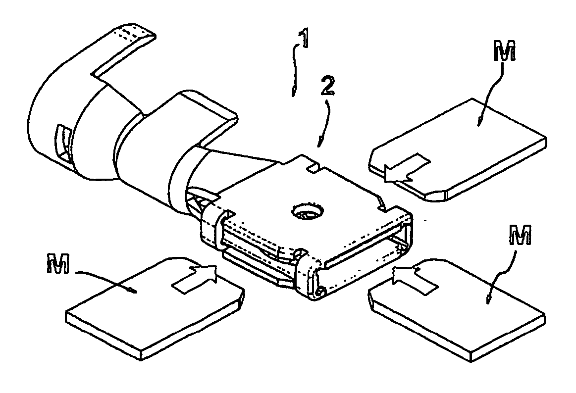
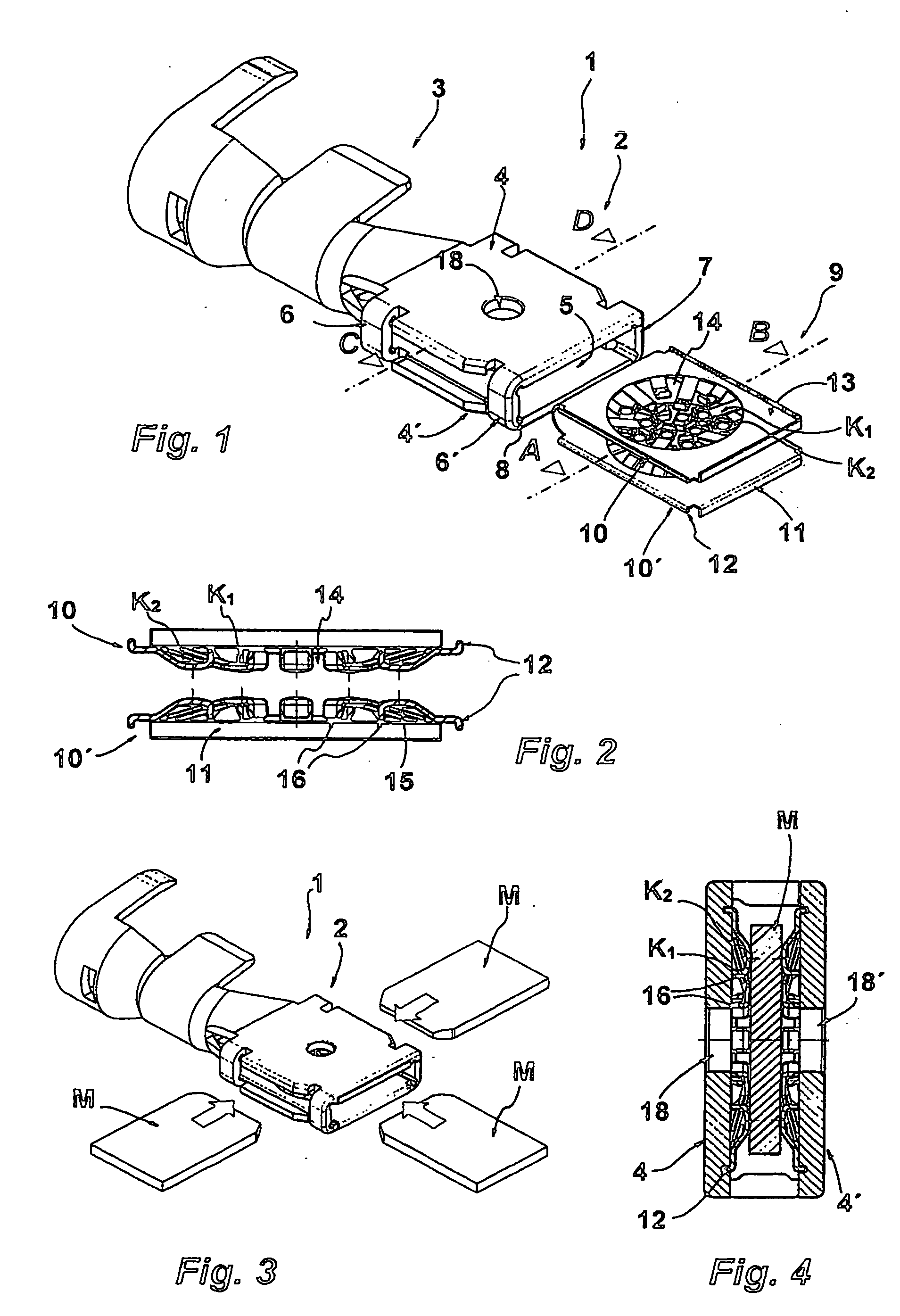
[0020] Referring now to FIG. 1, an electrical socket (receptacle) contact 1 in accordance with an embodiment of the present invention is shown. Socket contact 1 includes a socket (receptacle) housing 2. Housing 2 generally has a three-dimensional rectangular configuration. Housing 2 includes two lateral plates 4, 4′. Lateral plates 4, 4′ generally have corresponding rectangular or square surface areas bounded by four sides. Lateral plates 4, 4′ are spaced apart from one another and run parallel to one another to define an interspace therebetween. Lateral plates 4, 4′ border an opening 5 on a first side of housing 2 and border three other openings on the remaining three sides of the housing. Each opening leads into the interspace between lateral plates 4, 4′. Opening 5 serves as a front face of the housing.

[0021] A crimping extension 3 is integral with the opening on the second side of housing 2 which is opposite to opening 5. Crimping extension 3 connects an electrical conductor s...


PUM


Abstract

An electrical socket contact for high-current applications includes a cage-like receptacle housing having two lateral plates on opposite sides. The lateral plates forming an interspace therebetween for holding a complementary plug contact. The socket contact further includes a contact plate insert arranged within the interspace of the lateral plates of the housing. The contact plate insert has a contact plate body extending parallel to the lateral plates of the housing. The contact plate body has a base and first and second contact plates. Each contact plate has first and second ends. The first ends of the contact plates are connected to the base of the contact plate body and the second ends of the contact plates each has a contact zone projecting away from the base of the contact plate body.

Description

CROSS-REFERENCE TO RELATED APPLICATIONS [0001] This is a continuation of International Application PCT / EP2005 / 003221, published in German, with an international filing date of Mar. 26, 2005, which claims priority to DE 10 2004 015 345.0, filed Mar. 30, 2004, the disclosures of which are both hereby incorporated by reference.BACKGROUND OF THE INVENTION [0002] 1. Field of the Invention [0003] The present invention relates to an electrical socket contact for high-current applications in which the socket contact includes a cage-like receptacle housing formed by two lateral plates on opposite sides and includes a contact plate insert arranged within the housing in which the contact plate insert has a contact plate body extending parallel to the lateral plates and in which contact zones connected to the contact plate body protrude out from the contact plate body. [0004] 2. Background Art [0005] An electrical socket (or receptacle) contact is part of an electrical plug-and-socket connector...

Claims


Application Information

Patent Timeline
IPC IPC(8): H01R13/187H01R4/18H01R13/11H01R13/115H01R13/20
CPCH01R4/185H01R13/113H01R2201/26H01R13/20H01R13/187
Inventor MOHS, WOLFGANGHEINEMANN, PATRICK
Owner KOSTAL KONTAKT SYST
Why Eureka
Try Eureka