Measuring tool

a technology of measuring tools and moving parts, applied in the field of measuring tools, can solve the problems of time-consuming and labor-intensive assembly work, inability to achieve good operability, and inability to smoothly move the spindle, and achieve the effect of smooth movement of the movable member

Active Publication Date: 2007-03-29
MITUTOYO CORP
View PDF5 Cites 13 Cited by
  • Summary
  • Abstract
  • Description
  • Claims
  • Application Information

AI Technical Summary

Benefits of technology

[0020] An object of the present invention is to provide a measuring tool in which a biasing force for biasing a feed roller toward a movable member does not change no matter whether the feed roller is forward fed or reverse fed, so that the movable member can be smoothly moved, and good operability can be achieved.
[0029] According to this aspect of the present invention, since the forward feed roller exclusively for performing forward feed and the reverse feed roller exclusively for performing reverse feed are provided, the biasing force of the biasing mechanism applied to the movable member will not change no matter whether the forward feed is performed or the reverse feed is performed. Thus, the movable member can be smoothly moved both in the forward direction and in the reverse direction.
[0030] Further, since the user holds the workpiece with the left hand, grasps the body frame of the measuring tool with the right hand and rotates the outer roller with the right thumb to move the movable member, the operation can be easily performed with one hand.
[0031] Further, since the forward feed roller and the reverse feed roller are constantly biased by the biasing mechanism toward the direction in which the forward feed roller and the reverse feed roller are brought into contact with the movable member, idle running caused by wear of the outer peripheral faces of the forward feed roller and the reverse feed roller can be prevented, and thereby there is no concern that the measurement can not be performed.
[0034] According to this aspect of the present invention, since being configured by the main gear and the sub-gears, the power transmitter can have a relatively simple structure as a power transmitter built in the feeding mechanism. Also, by being combined with the biasing mechanism, the outer peripheral faces of the forward feed roller and the reverse feed roller can be constantly biased toward the direction in contact with the movable member. Further, since there is no slip between the gears, the rotation of the outer roller can be securely transmitted to the forward feed roller and the reverse feed roller.
[0038] According to this aspect of the present invention, since two side surfaces of the trapezoidal groove formed on the outer periphery of each of the forward feed roller and the reverse feed roller respectively contact two adjacent corners of the rectangular cross section of the movable member, the forward feed roller and the reverse feed roller can constantly be positioned at the center of the movable member in the axial direction of the forward feed roller and the reverse feed roller. Thus the forward feed roller and the reverse feed roller can operate stably so as to smoothly move the movable member.

Problems solved by technology

However, in the micrometer described in the above document, since the feeding mechanism is configured by the rack and the pinion, there will arise the following problem.
Specifically, when performing assembling adjustment during manufacture, since positioning the rack and the pinion (for example, adjustment of a backlash) is difficult to do, the assembling work becomes time-consuming and labor-consuming.
However, with the feeding mechanism having the aforesaid feed roller, since the spindle is moved by a common feed roller both when forward feed is performed for moving the spindle toward the side of the anvil and when reverse feed is performed for moving the spindle toward the side opposite to the anvil, there will arise the following problems.
Thus, even though the spindle can be smoothly moved by a biasing force of the spring when performing the reverse feed, in the case where the forward feed is performed, since a biasing force caused by the rotation of the outer roller in the forward direction is applied to the feed roller in an opposite direction to that of the biasing force of the spring, the feed roller will be moved in the direction away from the spindle, and thereby the spindle can not be smoothly moved.
Since the biasing force for pressing the outer periphery of the feed roller toward the spindle changes depending on whether the spindle is moved in the forward direction or in the reverse direction, good operability can not be achieved.

Method used


Image

  • Measuring tool
  • Measuring tool
  • Measuring tool

Examples


Embodiment Construction

)

[0046] An embodiment of the present invention will be described below with reference to the attached drawings.

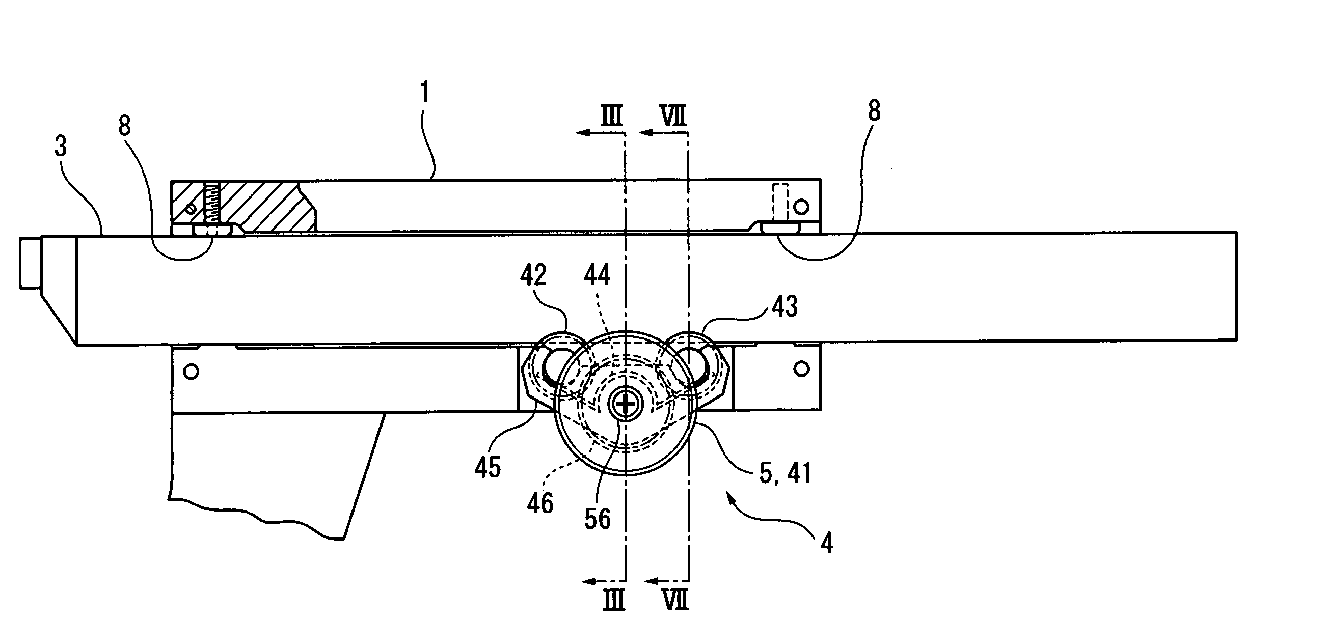
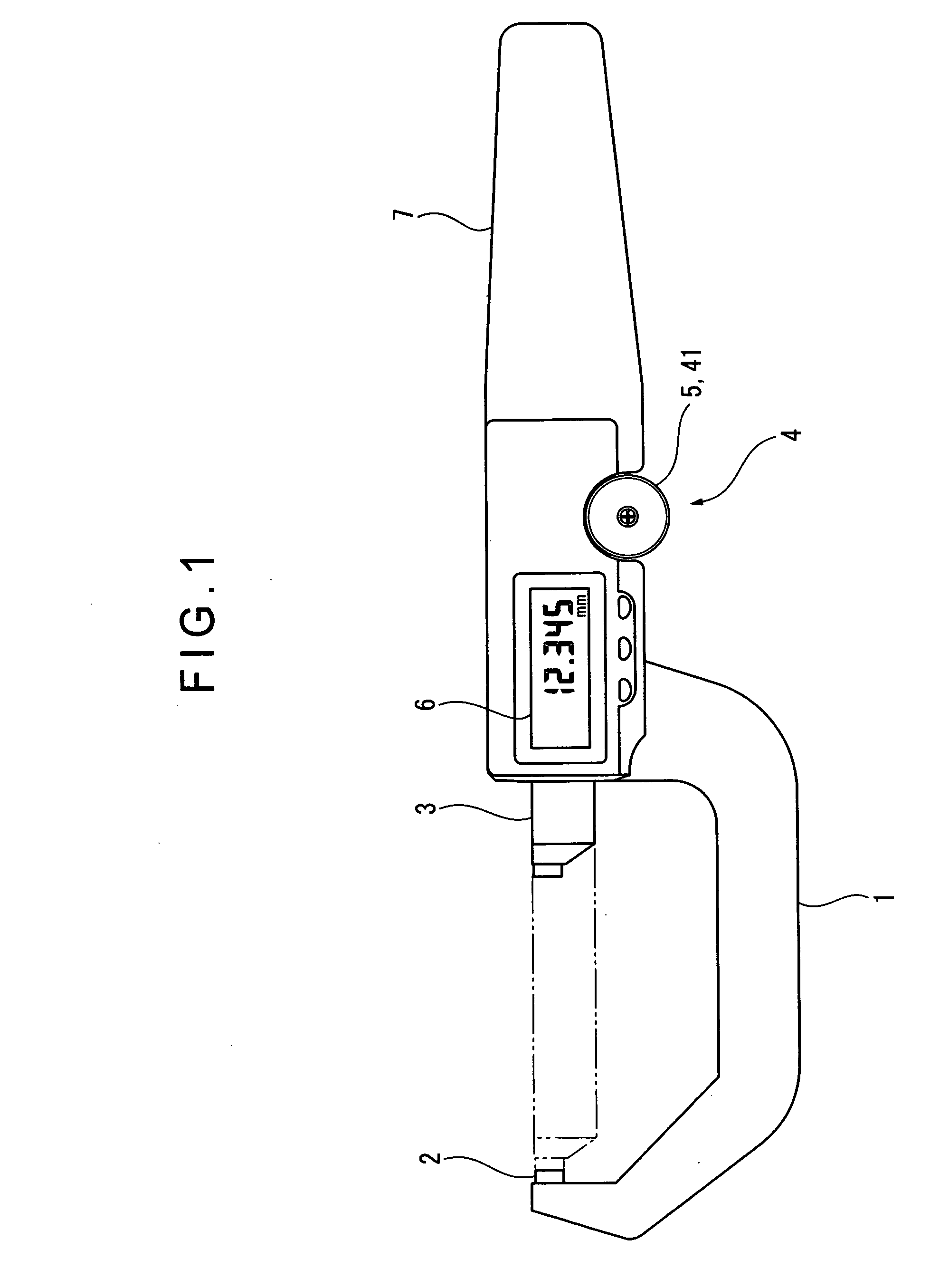
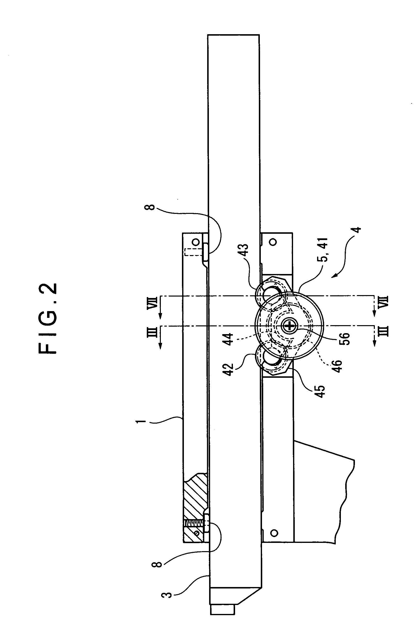
[0047]FIG. 1 is a front elevational view showing a measuring tool according to the embodiment. FIG. 2 is a partly enlarged view of a feeding mechanism of the measuring tool. FIG. 3 is a cross section taken along line III-III of FIG. 2. FIG. 4 is a cross section showing a ratchet mechanism, which is taken along line IV-IV of FIG. 3. FIG. 5 is a cross section taken along line V-V of FIG. 3. FIG. 6 is an illustration explaining a power transmitter. FIG. 7 is a cross section taken along line VII-VII of FIG. 2.

[0048] As shown in FIG. 1, the measuring tool of the present embodiment includes a U-shaped body frame 1, an anvil 2 provided on one end of the body frame 1, a slider 3 as a movable member provided on the other end of the body frame 1, a feeding mechanism 4 that moves the slider 3, an encoder (not shown) that detects a displacement of the slider 3, the encoder being arra...


PUM


Abstract

A measuring tool has a slider (3) supported to a body frame (1) and a feeding mechanism (4) for moving the slider in axial direction. The feeding mechanism includes: an outer roller (41) rotatably supported to the body frame (1); a forward feed roller (42) disposed between the outer roller (41) and the slider (3) at a position closer to a forward side of the slider (3) relative to the outer roller (41); a reverse feed roller (43) disposed at a position on a reverse side; a roller holder (45) supporting these feed rollers to allow them to move along the circumference around the axis of the outer roller; a first leaf spring (44) that biases these feed rollers toward the slider side; and a power transmitter (46) connecting the outer roller (41) to these feed rollers to transmit the rotation of the outer roller to the feed rollers.

Description

BACKGROUND OF THE INVENTION [0001] 1. Field of the Invention [0002] The present invention relates to a measuring tool. More specifically, the present invention relates to a measuring tool in which a movable member is moved to hold a workpiece, where a dimension or a profile of the workpiece is measured from a displacement of the movable member. [0003] 2. Description of Related Art [0004] There are conventionally known measuring tools in which a spindle thereof is moved in the axial direction to hold a workpiece, where a dimension or a profile of the workpiece is measured from the displacement of the spindle. Examples of such measuring tools include a micrometer (refer to, for example, U.S. Pat. No. 4,420,887, FIG. 9, FIG. 10, etc.). [0005] The micrometer includes a U-shaped body frame, an anvil provided on one end of the body frame, a spindle supported on the other end of the body frame, the spindle being advanceable and retreatable relative to the anvil in the axial direction, and ...

Claims


Application Information

Patent Timeline
Patent Type & Authority Applications(United States)
IPC IPC(8): G01B5/00
CPCG01B3/205G01B3/18
Inventor SUZUKI, MASAMICHI
Owner MITUTOYO CORP
Why Eureka
Try Eureka