

Night vision monocular housing and universal system for using same in various applications
- Summary
- Abstract
- Description
- Claims
- Application Information
AI Technical Summary
Benefits of technology
Problems solved by technology
Method used
Image

Examples
first embodiment
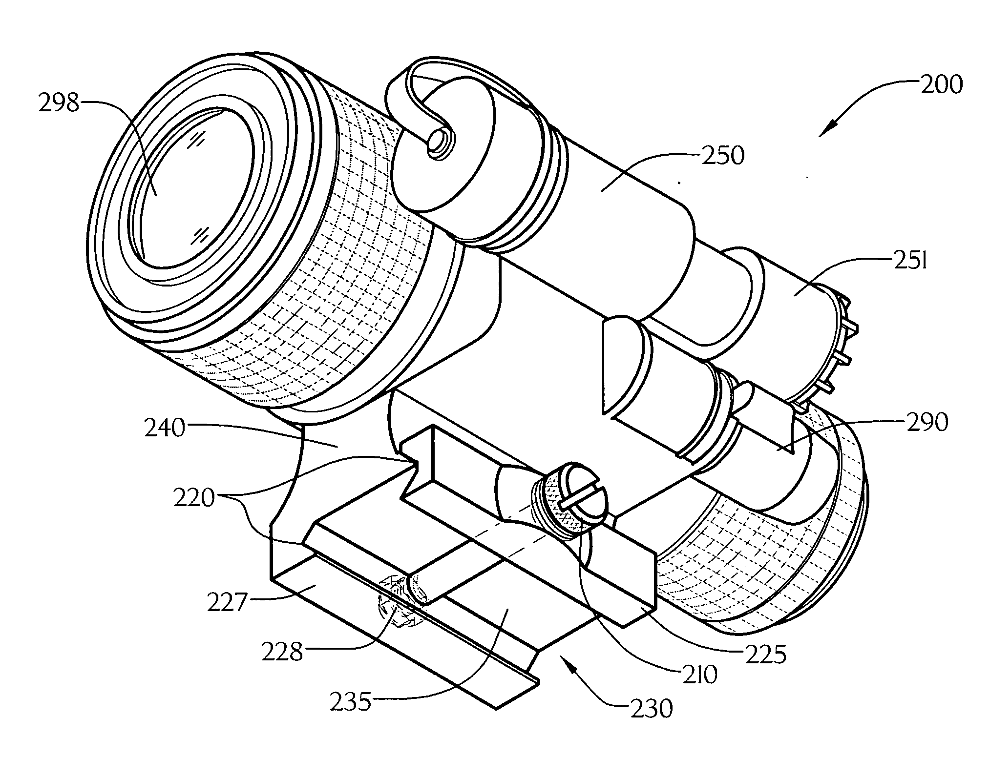
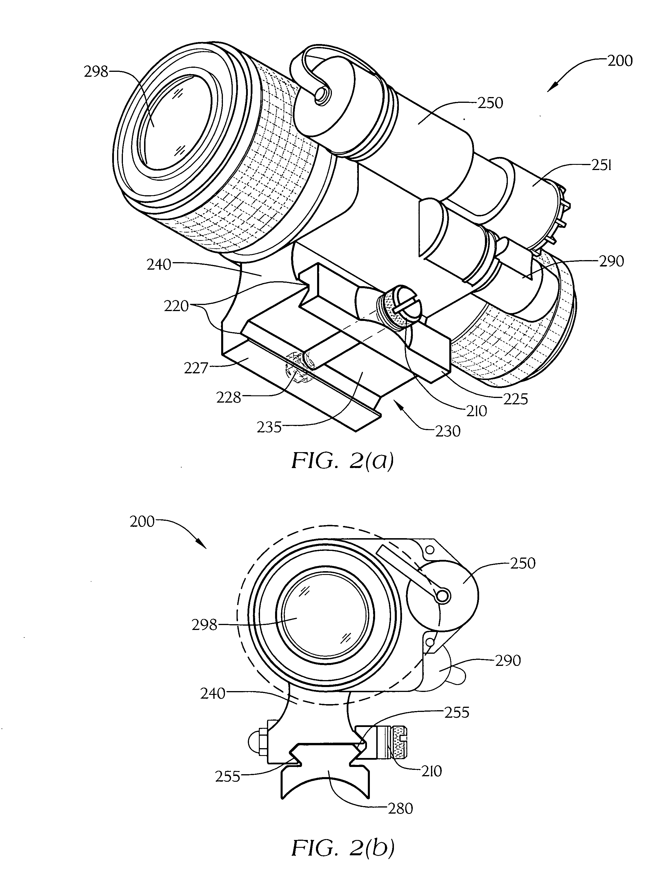
[0041] Turning now in detail to the appended drawings, particularly FIGS. 2-3, therein illustrated is a novel night vision monocular housing 200 embodying the concepts of the present invention. Monocular housing 200 is primarily cylindrical and hollow to accept the standard components of a night vision device, including but not limited to ocular 298 and objective lenses (not shown) and an image intensifier tube (not shown). The monocular housing has provided thereon a battery compartment 250 for containing the power source and a power switch 290. Optional infrared navigation light may have an adjustable focus knob 251 over it making it able to focus infrared light out to varying distances from the operator. This assists the operator in viewing under extreme low light or no light conditions, for example, indoors with no light present, since infrared light is below the discernible human visible spectrum, but can be seen with night vision equipment. Additional accessories are a sacrifi...
embodiment 500
[0052] To accommodate the present invention, however, this bracket 600 can be provided with a short picatinny rail 280, 380, 480 in place of the attachment provisions provided with known headgear adapters. This would enable the rail grabber clamping apparatus 230, 330, 430, 530 (FIGS. 2(a), 4(a), 6(a), 8) of the present invention to quickly attach and detach from an otherwise existing headgear adapter. The headgear adapter 600 to be used in conjunction with the monocular 200, 300, 400, 4000 (FIGS. 2, 4, 6, and 11) of the present invention or the clip-on embodiment 500 of FIG. 8, would have to be manufactured having a different arc angle for proper eye relief. The headgear adapter of the prior art mounts closely to the surface of the prior art monocular housing. Due to the raised portion 240, 340, 440, 540, 4400 on the monocular housing 200, 300, 400, 500, 4000 of the present invention, the adapter 600 to be used in conjunction with the present invention must have its mounting provis...
PUM
 Abstract
Description
Claims
Application Information