
Bat for upright piano

a bat and upright technology, applied in the field of upright bats, can solve the problems of deformation of the groove, and lateral hobble of the hammer assembly, and achieve the effect of easy adhesion to the bat, convenient assembly of the bat, and high adhesion

Inactive Publication Date: 2007-03-29
KAWAI MUSICAL INSTR MFG CO
View PDF2 Cites 3 Cited by
  • Summary
  • Abstract
  • Description
  • Claims
  • Application Information

AI Technical Summary

Benefits of technology

The present invention provides a bat for an upright piano that can ensure stable swing movements of a hammer to generate a proper piano sound even if the hammer assembly has a centroid that is laterally asymmetric about a center pin. The bat is supported by the center pin and has a pin holding groove and a metal plate attached to the bat body, which are engaged with the center pin. The center pin is sandwiched between the bat body and the metal plate, and the two are in engagement with each other. This design prevents the center pin from moving and ensures stable support of the bat and hammer. The bat also has a pin retaining groove and a metal plate attached to the bat body, which are engaged with the center pin. The center pin is in engagement with the bat body and metal plate at four circumferential points without play, and the spacing between the center pin and the pin holding groove is narrower towards the bottom to effectively prevent deformation of the bat and hammer. The pin holding groove also has a pair of stopper surfaces that prevent the center pin from moving outward along the inclinations, further stabilizing the hammer swing.

Problems solved by technology

However, the conventional bat described above implies the following problems.
Consequently, the hammer assembly laterally hobbles and therefore cannot swing with stability.
Also, such hobbling can result in deformation of the groove, and a gap between the center pin and groove.
In this event, the hammer assembly becomes wobbly, possibly resulting in a failure in stable pivotal movements of the hammer assembly, the inability of the hammer head to strike a string at a proper striking position, and a failure in generating a proper piano sound.
However, if the center pin varies in diameter, a gap is developed between the groove and center pin when the diameter is smaller, whereas the center pin cannot be brought into engagement with the groove when the diameter is larger.
Therefore, even such variations in diameter that can be generally assumed, can cause rather unfavorable situations in view of the stability.

Method used


Image

  • Bat for upright piano
  • Bat for upright piano
  • Bat for upright piano

Examples


Embodiment Construction

[0033] In the following, a preferred embodiment of the present invention will be described in detail with reference to the accompanying drawings.

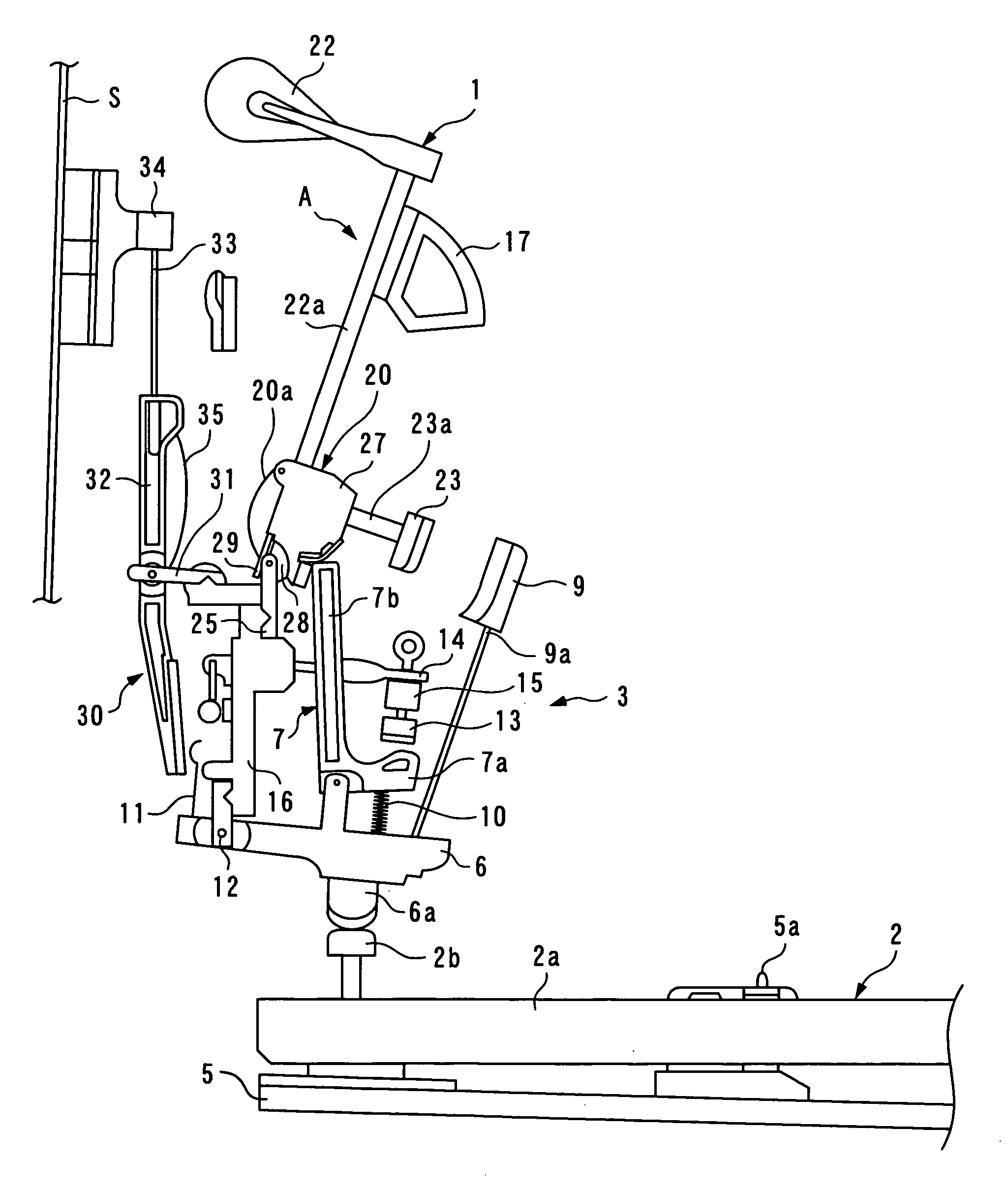
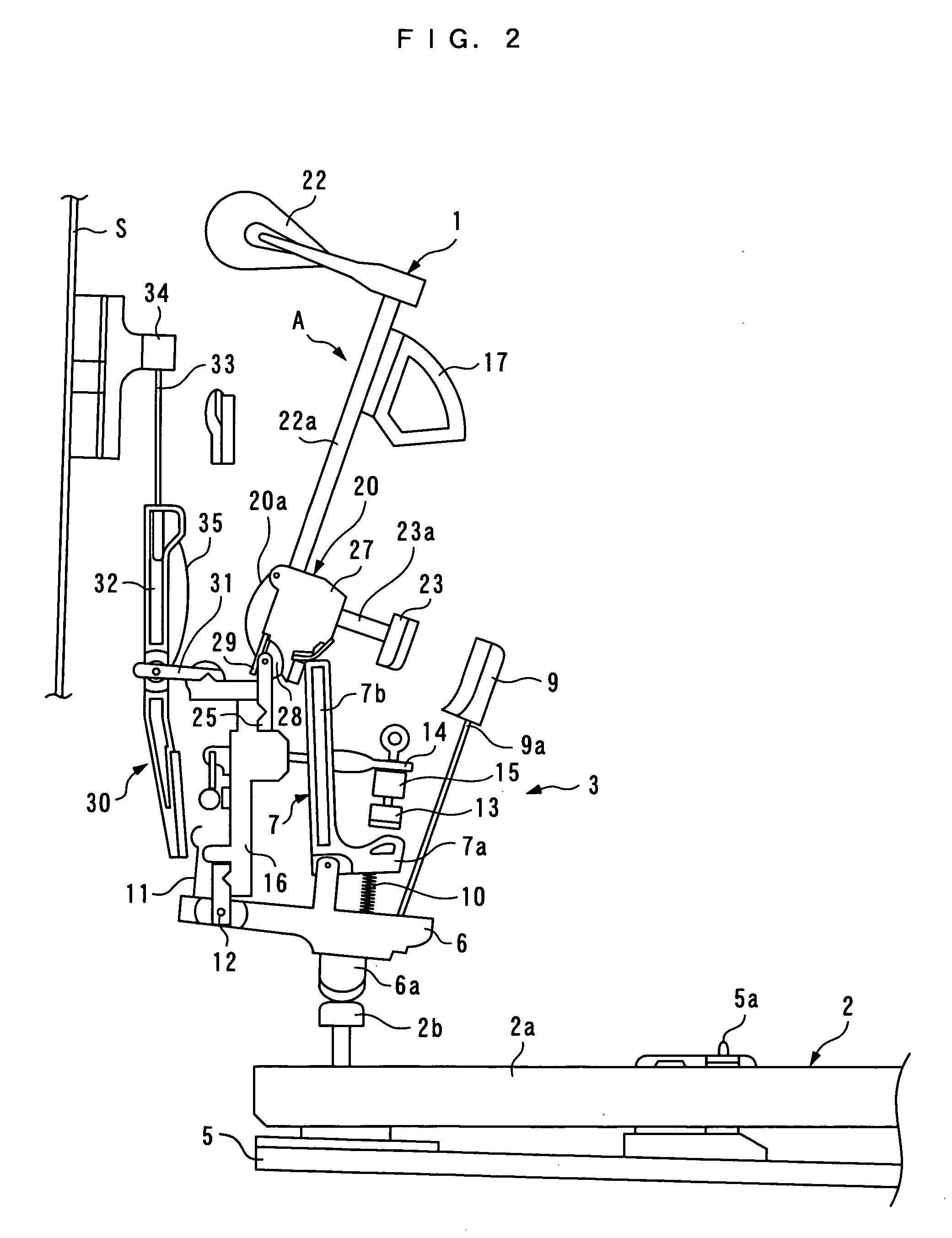
[0034]FIG. 2 illustrates an action 3, to which a bat 20 for an upright piano according to one embodiment of the present invention is applied, together with a hammer 1, a keyboard 2 and the like, in a key released state. In the following description, assume that, as viewed from a player side, the front side of the upright piano is called the “front,” and the back side of the same, the “rear.”

[0035] The keyboard 2 comprises a large number of keys 2a (only one of which is shown) arranged side by side from left to right (in a depth direction in FIG. 2), and each key 2a is swingably supported by a fulcrum which is a balance pin 5a implanted on a keybed 5.

[0036] The action 3 is attached to brackets (none of which is shown) arranged at a left and a right end of the keybed 5, respectively, above the rear end of the keyboard 2, and arranged to ext...


PUM


Abstract

A bat for an upright piano is provided for ensuring stable swinging movements of a hammer to generate a proper piano sound even if a hammer assembly has the centroid which is laterally asymmetric about a center pin. The bat for an upright piano is supported by the center pin having a circular cross section and arranged horizontally in a bat flange, in order to swing a hammer to cause the same to strike a string. The bat comprises a bat body integrally formed with the hammer, and having a linear pin holding groove in a back surface thereof, and a metal plate having a linear pin retaining groove in one side thereof, and attached to a back surface of the bat body such that the pin retaining groove extends in parallel with the pin holding groove, wherein the bat is pivotally supported by the center pin while the center pin is in engagement with the pin holding groove and the pin retaining groove, and the center pin is sandwiched between the bat body and the metal plate.

Description

BACKGROUND OF THE INVENTION [0001] 1. Field of the Invention [0002] The present invention relates to a bat for an upright piano, which is supported by a center pin disposed on a bat flange, and strikes a string by swinging a hammer in response to a key touch. [0003] 2. Description of the Prior Art [0004] A conventional bat for an upright piano is disclosed, for example, in Laid-open Japanese Patent Application No. 6-27934. This bat, which has a general structure, is provided on a key-by-key basis, in association with a hammer having a hammer head at an upper end thereof, a catcher and the like (hereinafter, the bat, hammer, and catcher are collectively called the “hammer assembly”). The bat has its lower end pivotally supported by a center pin of a bat flange. [0005] The bat flange has bat supports which protrude upward from a left and a right end, respectively, and a center pins extend horizontally between the left and right bat supports. One known bat has a bat body to which a bat...

Claims


Application Information

Patent Timeline
Patent Type & Authority Applications(United States)
IPC IPC(8): G10C3/18
CPCG10D3/163G10D3/173G10C1/02G10C3/16
Inventor YOSHISUE, KENJIABE, KIYOSHI
Owner KAWAI MUSICAL INSTR MFG CO
Learn More