Dead spindle chucking system with sliding sleeve

a chucking system and dead spindle technology, applied in the field of dead spindle chucking system, can solve the problems of motor stall, motor stall, transmission damage,

Inactive Publication Date: 2007-03-29
BLACK & DECKER INC
View PDF9 Cites 26 Cited by
  • Summary
  • Abstract
  • Description
  • Claims
  • Application Information

AI Technical Summary

Benefits of technology

[0013] The above and other features of the invention including various and novel details of construction and combinations of parts will now be more particularly described with reference to the accompanying drawings. It will be understood that the details

Problems solved by technology

However, if the chuck body is selectively grounded to the housing of the power driver and if the motor is run in the forward direction until the chuck jaws are tightened onto the accessory, then the m

Method used


Image

  • Dead spindle chucking system with sliding sleeve
  • Dead spindle chucking system with sliding sleeve
  • Dead spindle chucking system with sliding sleeve

Examples


Embodiment Construction

I. Example Embodiment Depicted in FIGS. 1-8

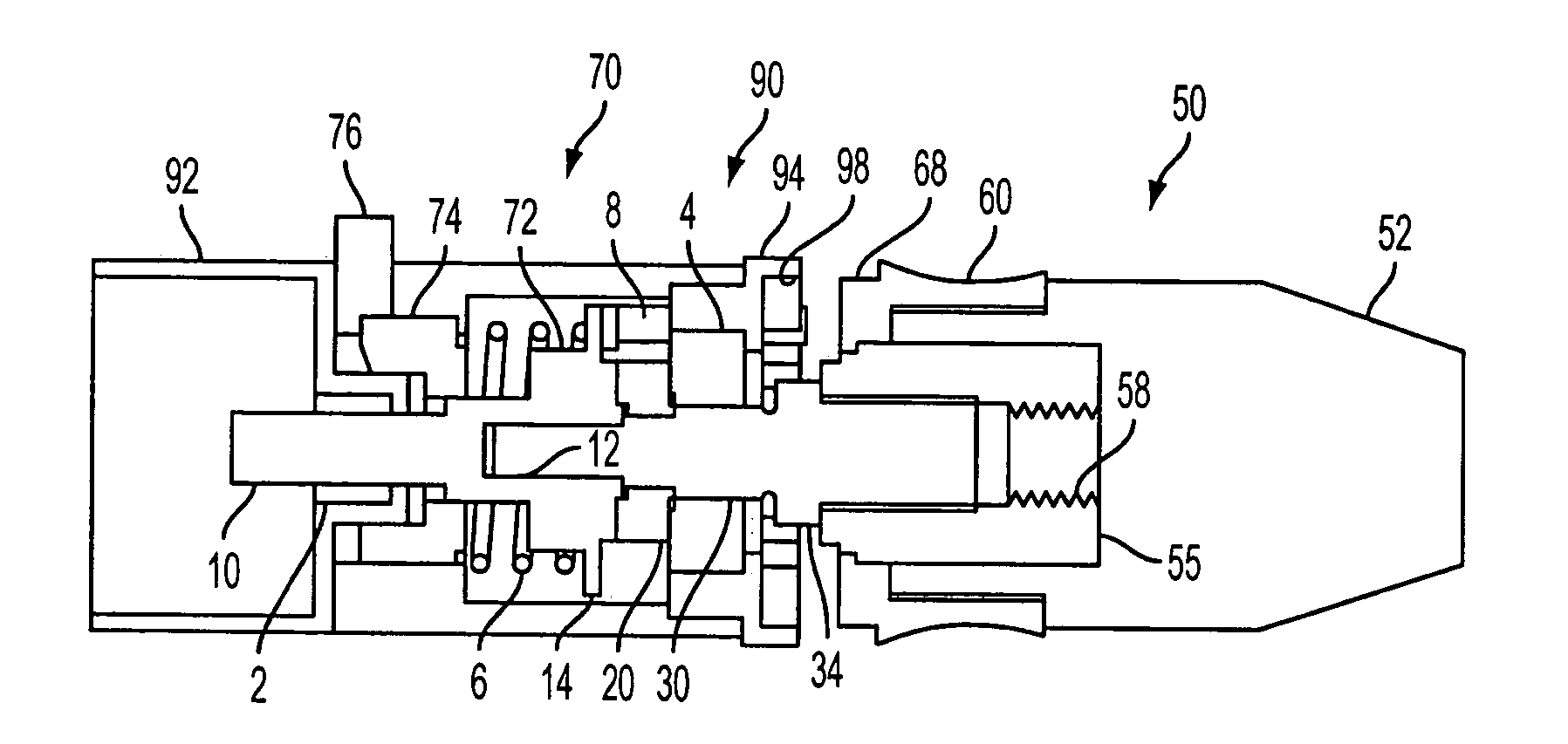
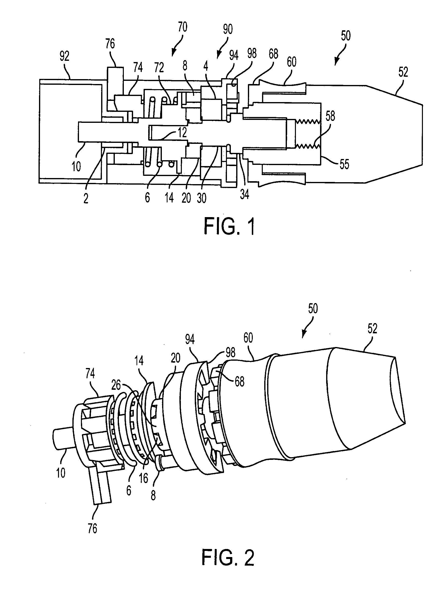
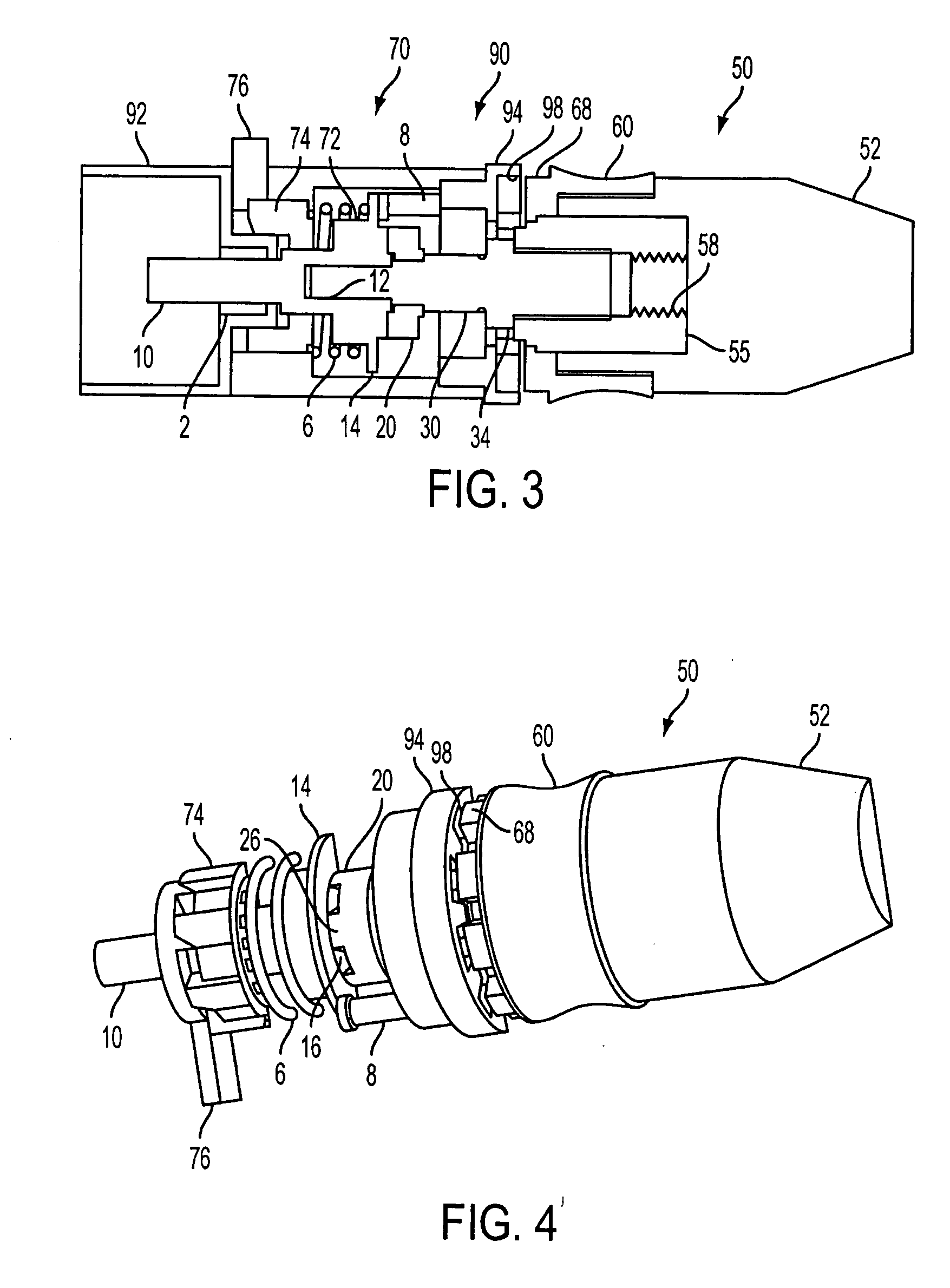
[0028]FIGS. 1-8 schematically show an example, non-limiting embodiment of a chucking system. The chucking system may include a tool chuck 50 that may be provided on a power driver (e.g., a drill) for holding an accessory (e.g., a drill bit). It will be appreciated, however, that the tool chuck 50 may be suitably implemented on a variety of power drivers (other than drills) for holding a variety of accessories (other than drill bits).

A. The Structure:

[0029] As shown in FIGS. 1 and 2, the tool chuck 50 may include a chuck body 52 that may support a chuck drive shaft 55, a sleeve 60 and chuck jaws (not shown). The chuck drive shaft 55 may be mounted for rotation on the chuck body 52. The chuck drive shaft 55 may be securely connected to an output shaft 30 of the power driver. A relative rotation between the chuck drive shaft 55 and the chuck body 52 may actuate the tool chuck 50 (i.e., open and close the chuck jaws).

[0030] For example, the...


PUM


Abstract

A power driver may include a housing, a tool chuck and a sleeve. The tool chuck may have a chuck body mounted for rotation on the housing and supporting threadless chuck jaws, and a chuck drive shaft mounted for rotation on the chuck body. The sleeve may be mounted on the tool chuck for adjustment into a DRILL DRIVE MODE to rotationally lock together the chuck body and the chuck drive shaft, and a CHUCK MODE to rotationally lock together the chuck body and the housing.

Description

CROSS REFERENCE TO RELATED APPLICATIONS [0001] This US non-provisional application claims priority under 35 USC §119 to U.S. Provisional Application No. 60 / 712,403 filed Aug. 31, 2005, the content of which is incorporated herein in its entirety by reference.BACKGROUND [0002] 1. Field of the Invention [0003] The present invention relates in general to tool chucks for attachment of accessories to power drivers, and more particularly to a tool chuck having chuck jaws that may be actuated via power from the driver's transmission. [0004] 2. Description of Related Art [0005] Commonly-assigned, copending provisional Application, entitled “TOOL CHUCK WITH POWER TAKE OFF AND DEAD SPINDLE FEATURES,” filed Apr. 19, 2005, and designated U.S. Application No. 60 / 672,503 (“the '503 application”), is hereby incorporated in its entirety by reference. The '503 application describes examples of a power driver that may be selectively operated in different modes, including a chuck mode. In the chuck mod...

Claims


Application Information

Patent Timeline
IPC IPC(8): E21B17/22
CPCB23B31/123B23B31/1253B23B2231/06B23B2231/38B25D16/006Y10S279/902B25D2216/0023B25D2216/0038Y10T408/65Y10T279/32Y10T279/17615B25D2211/064
Inventor PUZIO, DANIEL
Owner BLACK & DECKER INC
Why Eureka
Try Eureka