Substrate carrying tray

a substrate and carrying tray technology, applied in the direction of tables, transportation and packaging, packaging goods types, etc., can solve the problems of substrate breakage and stability cannot be achieved in stacked condition, and achieve the effect of simple structur

Inactive Publication Date: 2007-03-29
SHARP KK
View PDF32 Cites 23 Cited by
  • Summary
  • Abstract
  • Description
  • Claims
  • Application Information

AI Technical Summary

Benefits of technology

[0019] There is a case where the loaded object is a large object, for example, a substrate for a display panel, and the bottom surface of the substrate carrying tray is fully used to place a single loaded object. In such a case, by providing the upper and lower contact sections on the peripheral edge of the substrate carrying tray, it is possible to take a larger portio

Problems solved by technology

However, in such a substrate transport device in which each substrate is stored in a groove of the vertical hole, every substrate is held by ribs 205 only at its edge portion, and no other portions including its center portion are supported.
This has caused a fear that, when a substrate is used for a large size display panel, th

Method used


Image

  • Substrate carrying tray
  • Substrate carrying tray
  • Substrate carrying tray

Examples


Embodiment Construction

[0066] With reference to FIGS. 1(a) through 26, one embodiment of the present invention is described below.

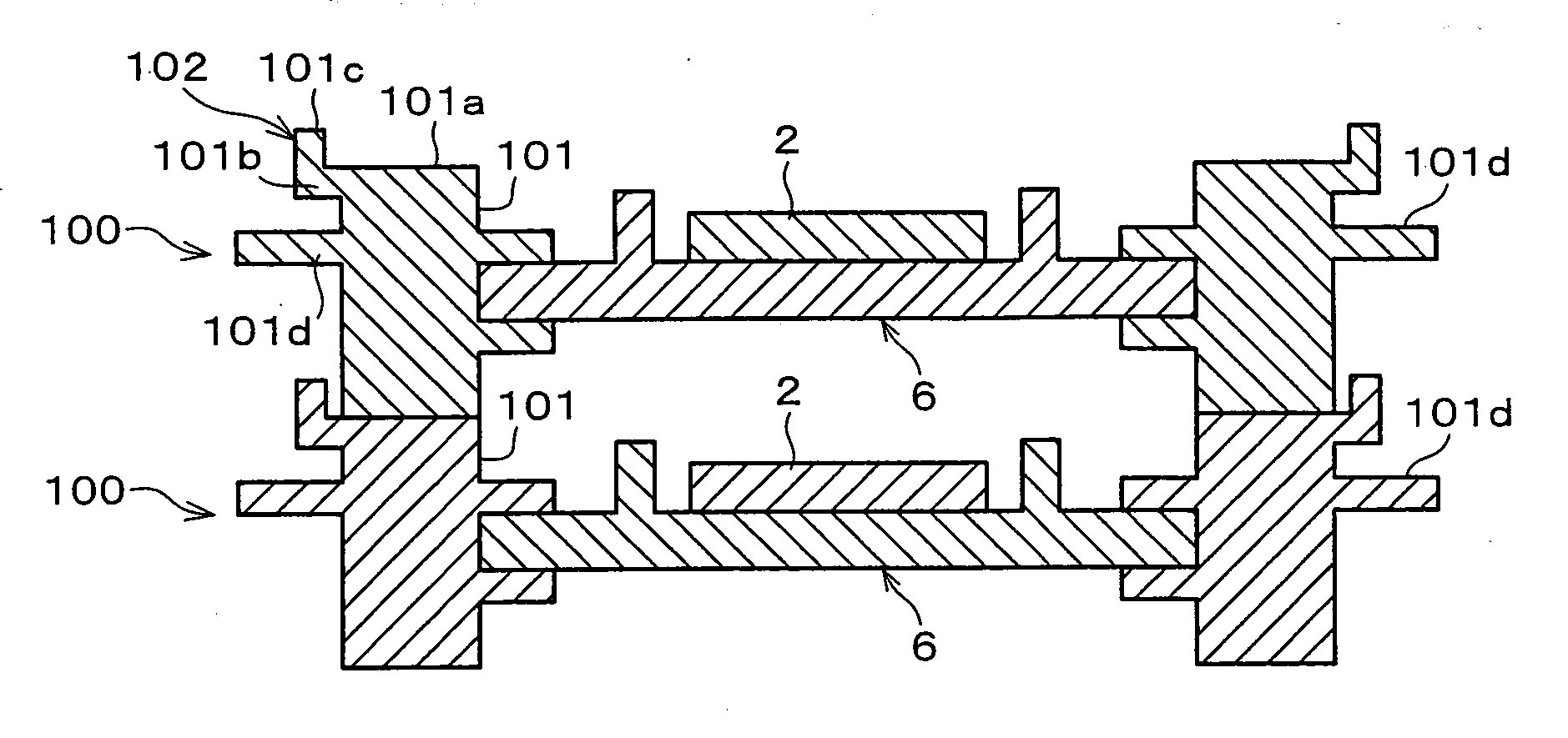
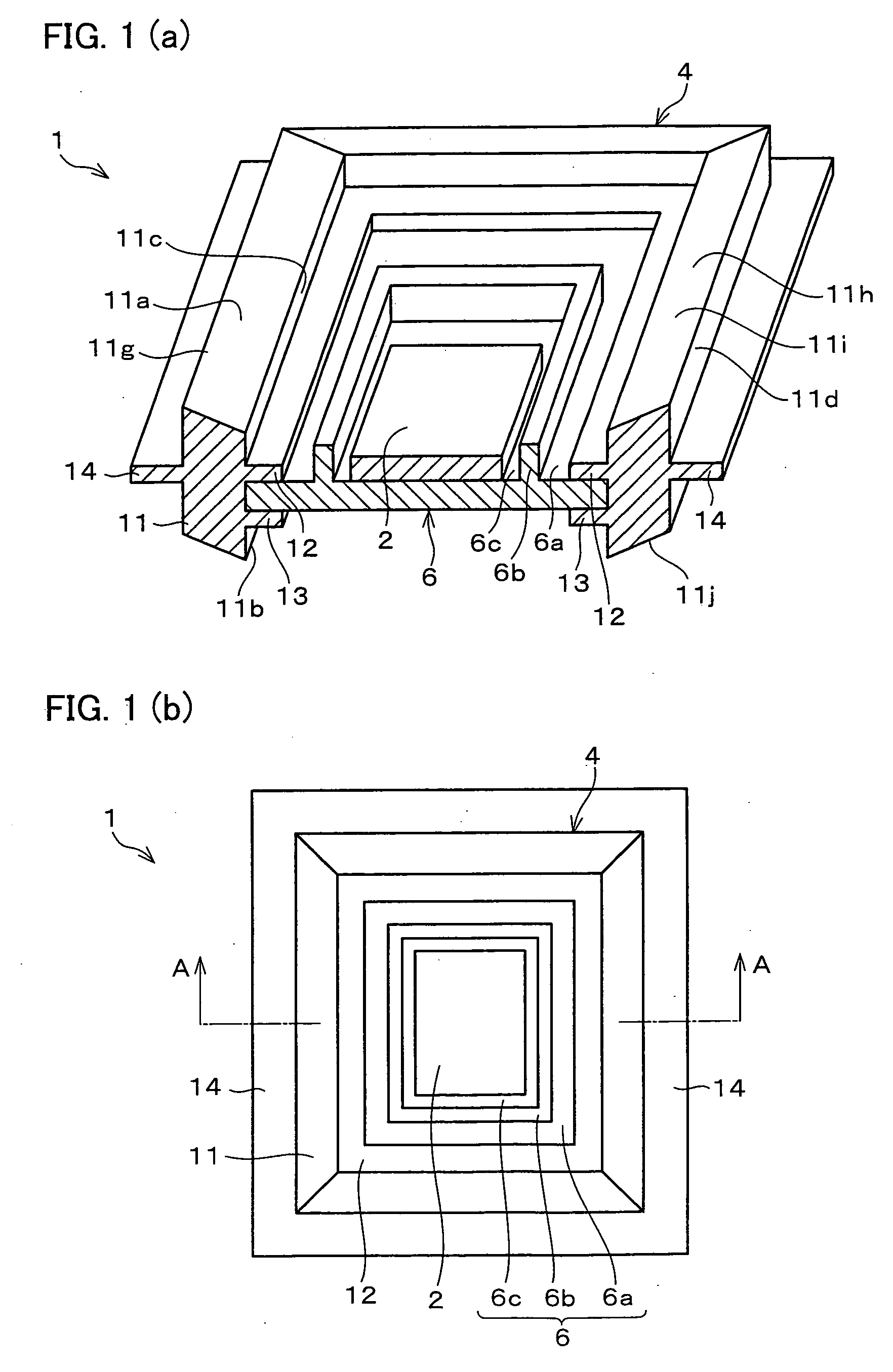
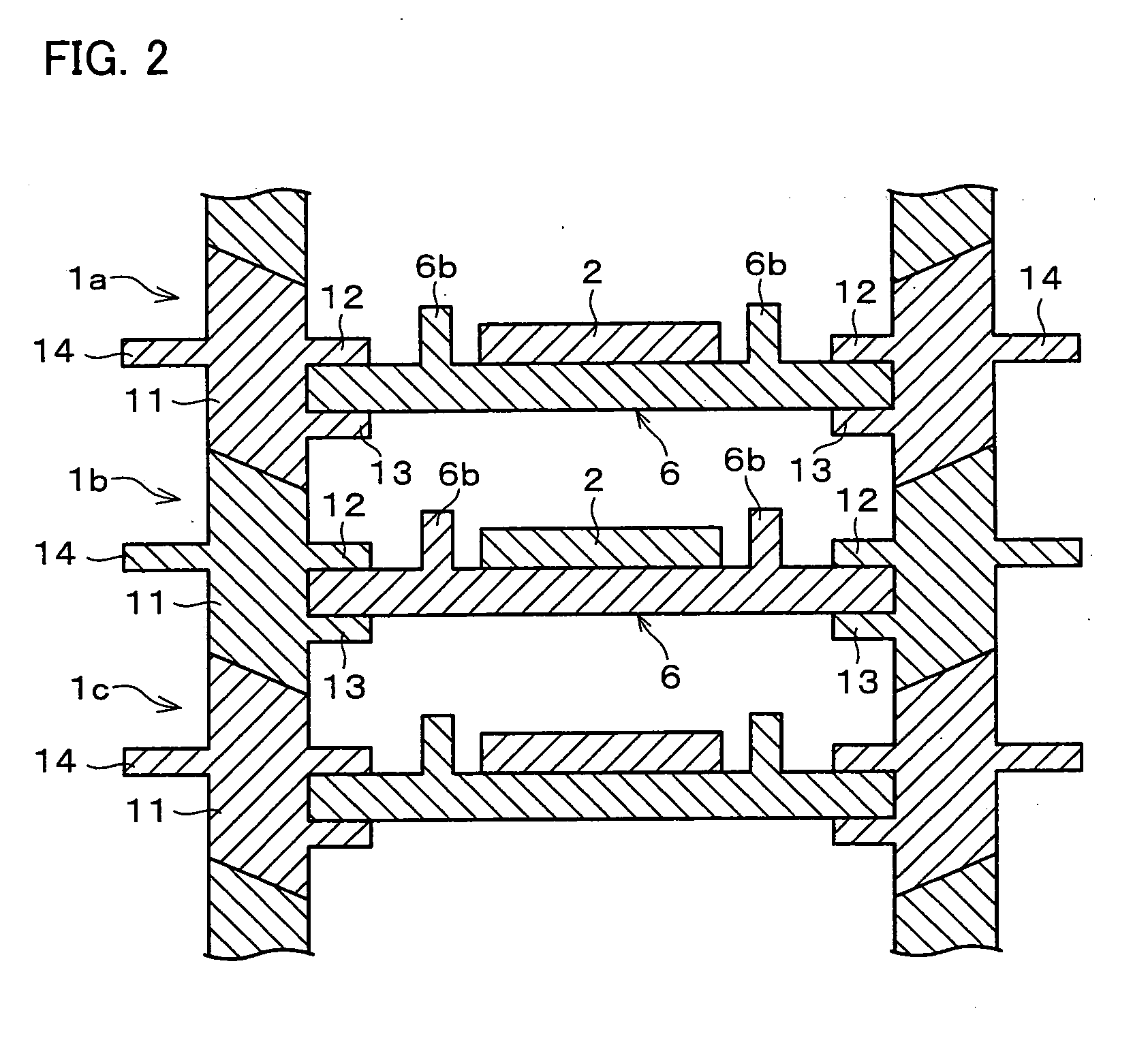
[0067] As shown in FIGS. 1(a) and 1(b), a substrate carrying tray 1 serves to load a loaded object, i.e., a glass substrate 2 (hereinafter, simply referred to as substrate 2) used for, for example, a liquid crystal display panel or the like. FIG. 1(a) shows a cross section of the substrate carrying tray 1 and the substrate 2 placed on the substrate carrying tray 1, which is taken along a vertical line on the center. In other words, FIG. 1(a) is an oblique view taken along line A-A shown in FIG. 1(b). Further, FIG. 1(b) is a top view of the substrate carrying tray 1 and the substrate 2 placed on the substrate carrying tray 1.

[0068] In the following description, as a standard condition, a substrate 6 is horizontally placed and constitutes an upper part of the substrate carrying tray 1. Thus, in FIG. 1(a), a direction toward the top of the sheet is an upper direction, and a dire...


PUM


Abstract

A stackable substrate carrying tray on which a substrate (2) is placed horizontally, includes an upper contact section; and a lower contact section, the upper contact section contacting a first substrate carrying tray (1) which is stacked above the substrate carrying tray (1), and the lower contact section contacting a second substrate carrying tray (1) which is stacked below the substrate carrying tray, the upper and lower contact sections being formed in a shape so as to move, when the first stackable substrate carrying tray is stacked above the substrate carrying tray, the first substrate carrying tray in such a direction that a center of gravity of the first substrate carrying tray is positioned vertically above a center of gravity of the substrate carrying tray (1). Thus, a substrate carrying tray is realized that eliminates a fear of breakage of loaded objects due to warping and contacting of the objects, and which can be stacked stably.

Description

TECHNICAL FIELD [0001] The present invention relates to a stackable substrate carrying tray which loads a loaded object. BACKGROUND ART [0002] In order to transport plural substrates used for a display panel or the like at one time, a substrate transport device as shown in FIG. 27 is commonly employed. The transport device shown in FIG. 27 is constituted by a packing material 201 having a rectangular vertical hole 203, which is made of foam polypropylene or the like. Further, the transport device is formed in a rectangular column (square column) having a bottom, and is provided with ribs 205 on an inner wall of the vertical hole 203. The number of the ribs 205 is one less than the number of substrates to be stored. With the ribs 205, the vertical hole 203 is partitioned and grooves 204 are formed. The number of the grooves 204 is equal to that of the substrates. Further, each of the grooves 204 receives a substrate 202 fitting in so that the substrate 202 is stored. By transporting ...

Claims


Application Information

Patent Timeline
IPC IPC(8): A47G19/08B65D21/02B65D85/38
CPCB65D85/38B65D21/0213B65D21/02B65D85/00
Inventor YOSHIZAWA, TAKENORI
Owner SHARP KK
Why Eureka
Try Eureka