
Osteosynthesis Device With Rapid Fixing Means

a technology of fast fixing and osteosynthesis, which is applied in the field of osteosynthesis devices to achieve the effects of reducing the risk of screw loosening, and facilitating regulation

Inactive Publication Date: 2011-03-03
WORCEL ALEXANDRE
View PDF11 Cites 6 Cited by
  • Summary
  • Abstract
  • Description
  • Claims
  • Application Information

AI Technical Summary

Benefits of technology

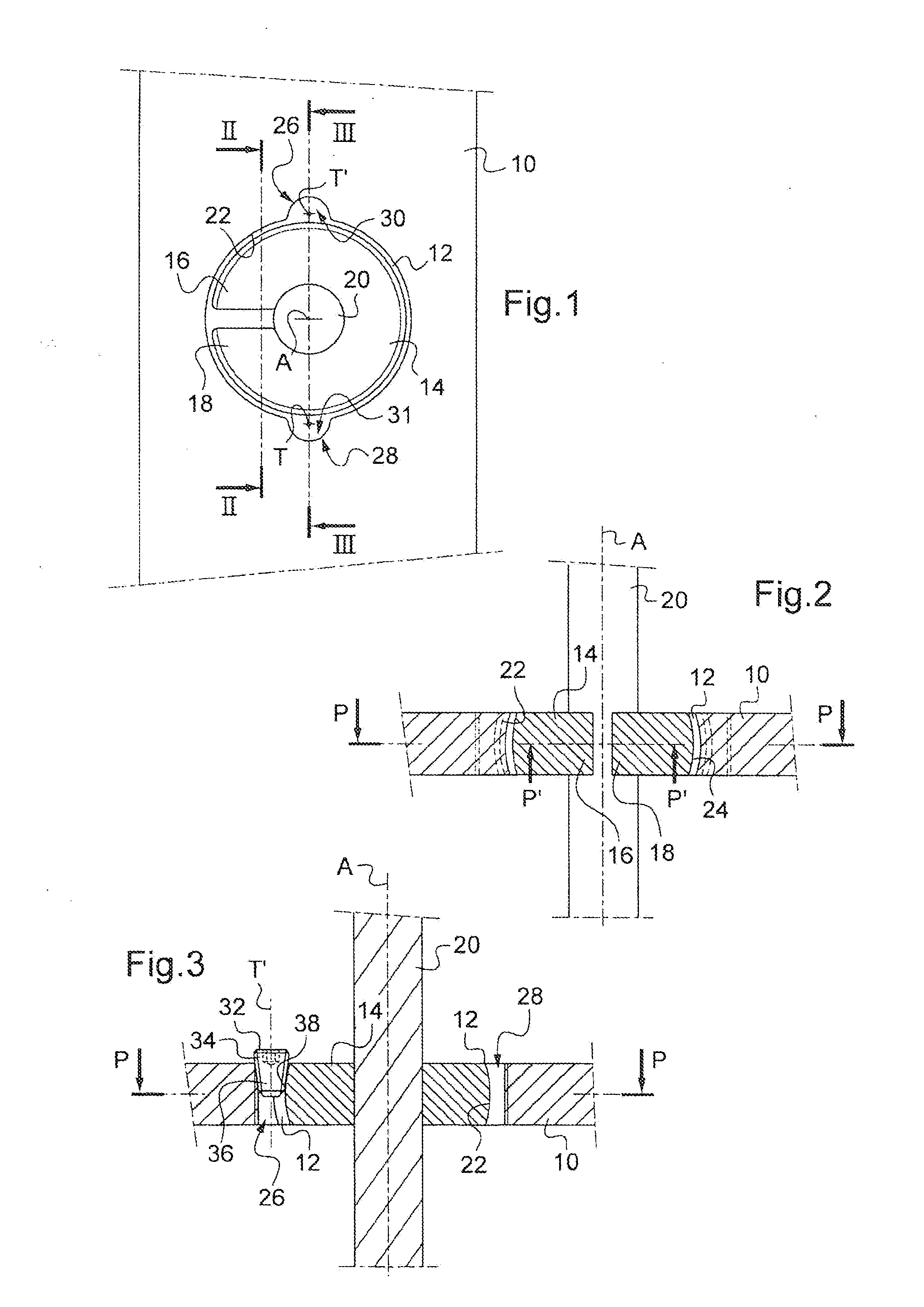
[0011]According to one advantageous implementation of the invention, said threaded opening, preferably with cylindrical symmetry, extends substantially perpendicular to said plate, so that the screw can apply significant pressure to the ring without the risk of working loose.
[0012]According to one particular embodiment, said threaded opening has an axis of symmetry that is appreciably inclined with respect to a perpendicular to said plate, so that said tapered screw has an extensive portion inside said recess, the generatrix of which is perpendicular to said plate. In that way, the pressure exerted by said extensive portion on the ring is distributed more symmetrically, and the risk of the screw working loose is reduced.
[0013]Furthermore, and according to a particularly advantageous embodiment variant, said threaded opening has an axis of symmetry substantially tangential to said inner edge, such that the threaded opening appears like a half cylinder on a circular base with an axial slit. In that way, when a tapered screw is screwed into the threaded opening when it is resting against the ring situated in the recess in the plate, it has a tendency to emerge laterally from its opening through the axial aperture applying pressure to the ring and does not lock by becoming jammed in the opening. By contrast, the pressure applied to the ring is easier to regulate by changing the extent to which the screw is screwed in.
[0014]In addition, and with a view to increasing the surface area over which the ring presses against the inner edge in spite of its inclination, said inner edge of said recess is concave so as to form a spherical annulus, whereas said ring defines a spherical segment to act like a ball inside said recess. This increase in bearing surface area not only makes for easier adjustment but also makes the connection between the ring and the plate more firm.

Problems solved by technology

When this pressure becomes too great in relation to the screwing effort, the tapered screw locks.

Method used


Image

  • Osteosynthesis Device With Rapid Fixing Means
  • Osteosynthesis Device With Rapid Fixing Means

Examples


Embodiment Construction

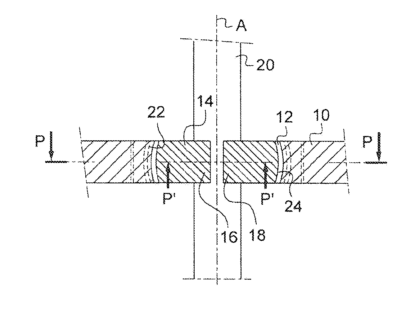
[0021]FIG. 1 partially illustrates an osteosynthesis plate 10 in which there is formed a circular recess 12 which passes right through it. A plate such as this quite obviously comprises a plurality of circular recesses staged along its length. Installed in the recess 12 is a circular ring 14 which is radially split so as to form two free ends 16, 18 facing one another. Furthermore, slideably mounted in the ring 14 is a pin 20 of circular cross section. FIG. 2 again shows the osteosynthesis plate 10 in the thickness of which the circular recess 12 is formed. The ring 14 is installed in this circular recess 12 while the pin 20, of longitudinal axis A, is slideably mounted in the ring 14 and oriented in a direction substantially perpendicular to the plane P defined by the plate 10. The ring 14 installed in the plate 10 is also able to guide the pin 20 in a translational movement in a piece of bone when the device is installed on a patient. It will be seen from the figure that the plane...


PUM


Abstract

The invention relates to an osteosynthesis device comprising a plate (10) and means for fixing a pin (20) that extends through the plate, in which the plate (10) includes a recess (12) for receiving the fixing means and the recess defines an inner edge (22), said fixing means comprising a ring (14) designed to received the pin (20) and screwable locking means (32). According to the invention, the plate (10) has a threaded opening (26) on the edge of the recess (12), which opens into the inner edge (22), while the ring (14) is slit radially. The screwable locking means comprise a screw (32) that can be screwed through the threaded opening (26) so as to bear against the ring (14) and cause the ring (14) to bear with force against a portion of the inner edge (22) and tighten the ring (14) on the pin (20).

Description

RELATED APPLICATIONS[0001]This application is a continuation of PCT / FR2009 / 000116, filed Feb. 2, 2009, which claims the benefit of FR0800556, filed on Feb. 1, 2008. The entire teachings of the above application(s) are incorporated herein by reference.FIELD OF THE INVENTION[0002]The present invention relates to an osteosynthesis device comprising a plate and fixing means allowing a pin to be held through said plate.[0003]One anticipated field of application is notably that of the reduction of fractures for which the plate extends along two bits of bone delimited by the fracture and at least two pins are installed through the plate and screwed respectively into said two bits of bone. In that way, because the two pins are held in a fixed position the one relative to the other by means of the plate, the two bits of bone are correspondingly held together. A device such as this is generally installed for a set period, of the order of about a month, during which the two bits of bone knit b...

Claims


Application Information

Patent Timeline
Patent Type & Authority Applications(United States)
IPC IPC(8): A61B17/80
CPCA61B17/60A61B17/8033A61B17/8047
Inventor WORCEL, ALEXANDRE
Owner WORCEL ALEXANDRE
Learn More