Apparatus for washing and dewatering pulp

a technology for washing and dewatering pulp, which is applied in the direction of moving filter element filters, filtration separation, and separation processes, etc. it can solve the problems of limiting the access provided by previously known solutions, limiting the working space of clearing plugs, and limiting the access to the press roll. , to achieve the effect of reducing the bulkiness of the external stationary pulp feeding system surrounding the apparatus, limiting access to the press roll, and reducing the bulkiness of the external stationary pulp feeding system

Inactive Publication Date: 2013-05-28
VALMET TECH INC
View PDF17 Cites 6 Cited by
  • Summary
  • Abstract
  • Description
  • Claims
  • Application Information

AI Technical Summary

Benefits of technology

[0017]In prior art roll presses, the pulp distribution device is stationarily mounted adjacent to the press roll, and when the pivotable side casing member is in an opened position, the stationary pulp distribution device limits accessibility when performing maintenance work, such as inspection, the exchange of press rolls, removal of plugs, and the cleaning the permeable outer surface or the region in proximity to the outer surface of the press roll, or the press nip. By mounting the pulp distribution device on the side casing member, the pulp distribution device is automatically moved away from the press roll when opening the side casing member, whereby improved accessibility to the different parts of the apparatus is provided, a larger portion of the outer surface of the first press roll is uncovered when the side casing member is opened, and the above-mentioned maintenance work is radically facilitated.
[0020]In this manner, the amount of stationary pipes of the external pulp feeding system associated with prior art apparatus, which provides the apparatus with pulp, and surrounds the apparatus and thereby limits access to the press rolls, is reduced, and the bulkiness of the external stationary pulp feeding system surrounding the apparatus is consequently reduced. Most particularly, the external stationary pipes connected to each pulp distribution device can be excluded. By this reduction of the external stationary pipe arrangement, accessibility when performing maintenance work of the above-mentioned types is further improved. When installing a prior art roll press, the external pipe arrangement for feeding pulp to the apparatus is mounted on site where the plant is located, and the pipe arrangement is often custom-made to be adapted to the environmental conditions at the plant. This installation work is time consuming and generates costs. By integrating the arrangement for transporting pulp from the inlet device to the pulp distribution device in the pivotable side casing member, the amount of work for mounting the external pipe arrangement is minimized, and time and money is saved.
[0021]Further, by providing the apparatus with one inlet device which distributes pulp to all flow channels, the number of connection points of the apparatus to the external pulp supply can be reduced, since only the inlet device needs to be connected to the external pulp supply, instead of connecting each pulp distribution device to the pulp supply, which facilitates installation on site. Advantageously, the inlet device is provided with only one inlet for connection to the external pulp supply. Thus, the present invention also contributes to standardization with regard to the plant and the pulp supply system, which facilitates installation of the apparatus. Advantageously, the apparatus comprises a stationary base unit positioned substantially below the first and second press rolls, which base unit houses the inlet device.

Problems solved by technology

The vat limits accessibility to the press roll, especially if the vat encloses a large portion of the circumference of the perforated outer surface of the press roll.
However, the access provided by these previously known solutions is limited, and these doors do not provide sufficient working room for clearing plugs.
However, there are still further installations and arrangements associated with the roll press, especially stationary external equipment adjacent to the roll press, which are bulky and impair accessibility when performing maintenance work, especially when making inspections, changing press rolls, removing plugs, and cleaning the perforated outer surface or the region in proximity to the outer surface of the press roll, or the press nip.

Method used


Image

  • Apparatus for washing and dewatering pulp
  • Apparatus for washing and dewatering pulp
  • Apparatus for washing and dewatering pulp

Examples


Embodiment Construction

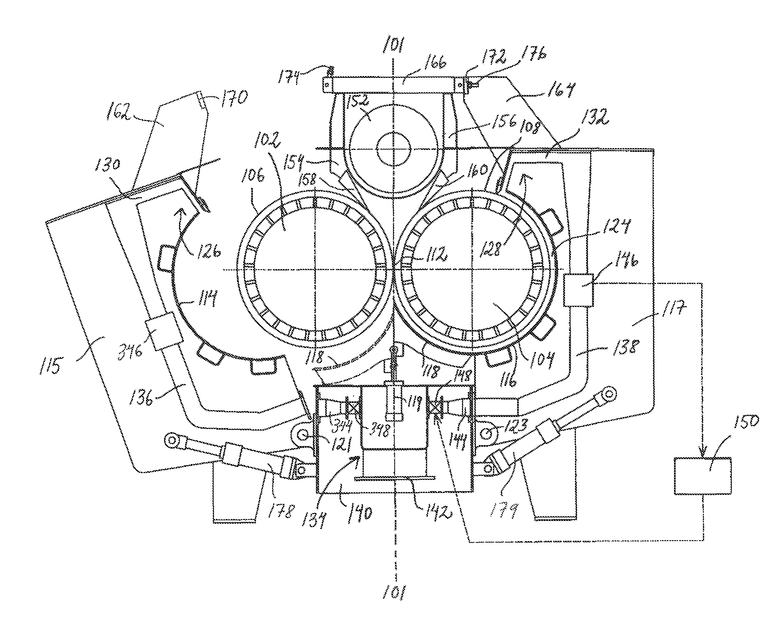
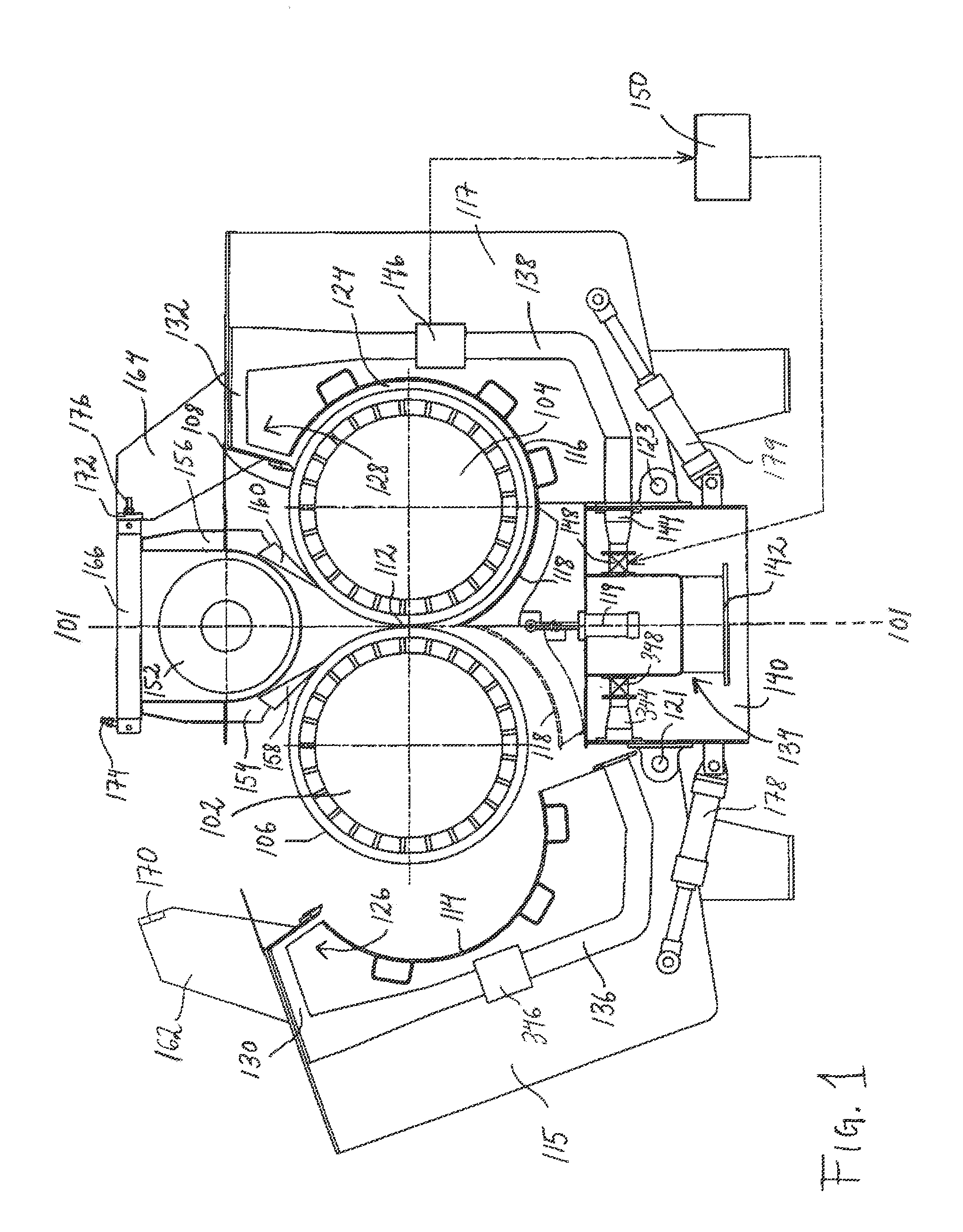
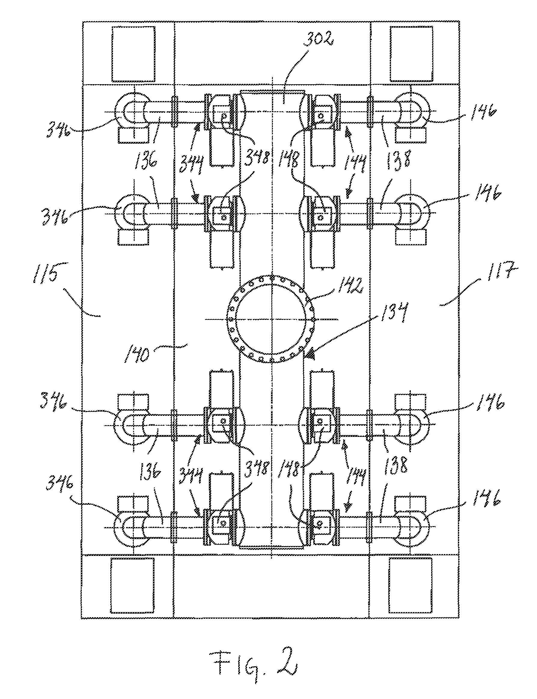
[0028]FIG. 1 shows an embodiment of the apparatus for washing and dewatering cellulose-containing pulp according to the present invention. The apparatus has a substantially symmetrical configuration with regard to a symmetry plane 101, and in FIG. 1, the left side of the apparatus, i.e. to the left of the symmetry plane 101, illustrates the apparatus in an opened position, whereas the right side of the apparatus, i.e. to the right of the symmetry plane 101, illustrates the apparatus in a closed and operating position. The apparatus comprises a first rotatable press roll 102 on the left side of the apparatus and a second rotatable press roll 104 on the right side of the apparatus, each press roll, 102 and 104, having a permeable outer surface, 106 and 108. The outer surface, 106 and 108, is perforated, i.e. provided with apertures, whereby the outer surface, 106 and 108, is permeable to filtrate pressed out of the pulp. The shape of the apertures is normally circular, but any shape i...


PUM

PropertyMeasurementUnit
permeableaaaaaaaaaa
axis of rotationaaaaaaaaaa
circumferenceaaaaaaaaaa

Abstract

Apparatus for washing and dewatering pump comprising a pair of rotatable press rolls with permeable outer surfaces, a casing comprising a vat in which the rolls are installed, and a feed for feeding the pulp to the gap formed between the vat and the press roll is disclosed. The vat includes a first side vat segment partially enclosing the first press roll and a second side vat segment partially enclosing the second press roll and casing members for each of the vat segments, the first casing member being pivotable about an axis of rotation and between closed and open positions, pulp distribution devices for distributing pulp onto the press rolls, at least one of the pulp distribution devices being mounted on the casing member whereby it is moved away from the press roll together with the casing member when it is opened.

Description

CROSS-REFERENCE TO RELATED APPLICATIONS[0001]The present application is a national phase entry under 35 U.S.C. §371 of International Application No. PCT / SE2008 / 051439 filed Dec. 11, 2008, published in English, which claims priority from Swedish Patent Application No. 0750008-5 filed Dec. 13, 2007, all of which are incorporated herein by reference.FIELD OF THE INVENTION[0002]The present invention relates to apparatus for washing and dewatering pulp, especially cellulose-containing pulp, comprising two rotatable press rolls having a permeable outer surface, between which the pulp is pressed, and a casing comprising a vat in which the press rolls are installed. The vat partly encloses the outer surface of each press roll and the vat comprises a first side vat segment which partly encloses the outer surface of the first press roll and a second side vat segment which partly encloses the outer surface of the second press roll. The casing comprises a first side casing member provided with ...

Claims


Application Information

Patent Timeline
Patent Type & Authority Patents(United States)
IPC IPC(8): B01D33/06D21F1/06
CPCD21C9/06D21F1/78D21D1/40D21C9/18B30B9/20
Inventor BYLANDER, JOHANPONTEN, FREDRIKLUNDBERG, JORGEN
Owner VALMET TECH INC
Why Eureka
Try Eureka