Split fan wheel and split shroud assemblies and methods of manufacturing and assembling the same

a technology of fan wheels and shrouds, which is applied in the direction of specific fluid pumps, liquid fuel engine components, non-positive displacement fluid engines, etc., can solve the problems of only medium speed roller mills and relative slowness, and achieve the effect of removal and installation

Active Publication Date: 2007-03-29
RILEY STOKER
View PDF9 Cites 14 Cited by
  • Summary
  • Abstract
  • Description
  • Claims
  • Application Information

AI Technical Summary

Benefits of technology

[0012] In its broadest terms, the present invention provides devices and systems for transporting a material, e.g., pulverized coal, suspended in a fluid, e.g., air, to a coal-fired burner, wherein the devices and systems are sectionalized to allow installation about and removal from a rotary element, e.g., a rotor shaft, and to methods of manufacture and installat

Problems solved by technology

However, they are relatively slow.
Although faster than ball-type tub

Method used


Image

  • Split fan wheel and split shroud assemblies and methods of manufacturing and assembling the same
  • Split fan wheel and split shroud assemblies and methods of manufacturing and assembling the same
  • Split fan wheel and split shroud assemblies and methods of manufacturing and assembling the same

Examples


Embodiment Construction

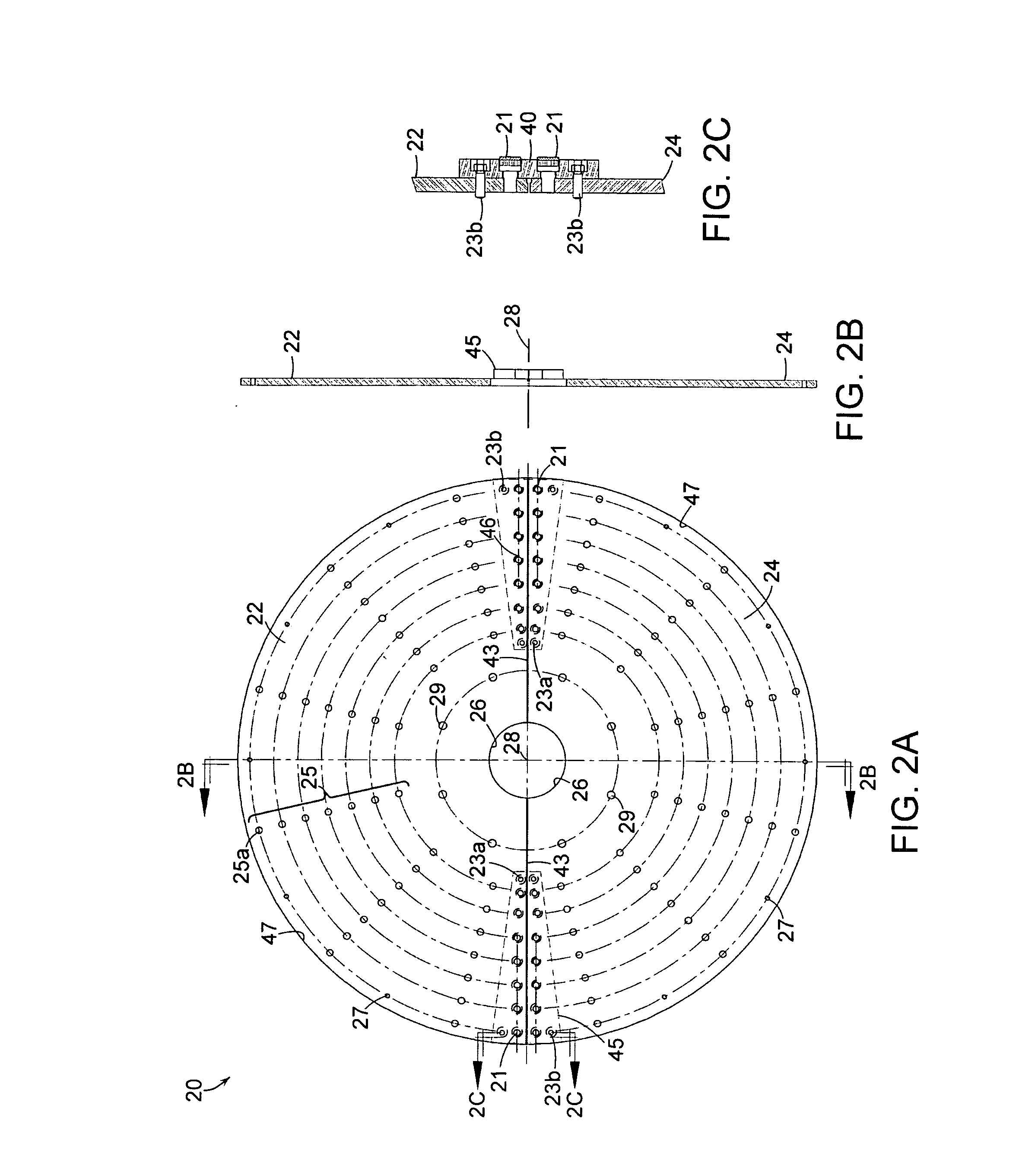
[0083] Referring to FIG. 2a-2c, an illustrative embodiment of a split fan wheel assembly 20 in accordance with the present invention will be described. In FIG. 2a, there is shown an embodiment of the split fan wheel assembly 20 that comprises a first fan wheel portion 22 and a second fan wheel portion 24. In a preferred embodiment, to conjoin the fan wheel portions 22 and 24, a plurality splice plates 45 and 46 is removably attached to the each of the fan wheel portions 22 and 24. Preferably, the splice plates 45 and 46 are trapezoidal or substantially trapezoidal in shape having a base, or longer, portion furthest away from the center of the fan wheel assembly 28.

[0084] Preferably, each of the first and second fan wheel portions 22 and 24 are semi-circular in shape and include a center cut-out region 26 that, likewise, is semi-circular in shape. In a preferred embodiment the dimensions of the center cut-out region 26 are structured and arrange to fit about a rotor section of a rot...


PUM

PropertyMeasurementUnit
Angleaaaaaaaaaa
Pressureaaaaaaaaaa
Sizeaaaaaaaaaa

Abstract

Devices and systems for transporting a material suspended in a fluid, e.g., pulverized coal, that can be assembled about a rotary element are disclosed. The devices and systems comprise a first portion or half of a fan wheel assembly, a second portion or half of a fan wheel assembly, and a plurality of splice plates for connecting the first portion of the fan wheel assembly to the second portion of the fan wheel assembly about the rotary element. Methods of manufacturing and assembling the sectionalized devices and systems are also provided.

Description

BACKGROUND OF THE INVENTION [0001] 1. Field of the Invention [0002] This invention relates to devices and systems to facilitate replacing wheels and blades, e.g., on a fan, on a rotary element and, more particularly, to split wheel assemblies, e.g., a fan wheel assembly, and split shroud assemblies for use on a high-speed attrition-type coal pulverizer. [0003] 2. Background of the Related Art [0004] In coal-fired furnaces, for purposes of improved and more efficient ignition, it is preferred to pulverize the coal to a fine powder before introducing it into the furnace for combustion. Coal pulverization involves systematically comminuting coal to a desired, preferably optimum size, e.g., a fine powder, prior to introduction into a coal-fired furnace. Currently, coal pulverization systems include ball-tube-type mills, vertical roller-type mills, and high-speed, attrition-type pulverizers. [0005] Ball-tube-type mills are low speed mills that have their origins in the 1930's and 1940's....

Claims


Application Information

Patent Timeline
IPC IPC(8): B02C13/00
CPCB02C13/12B02C13/288F04D7/045F04D29/2222F23K1/00Y10T29/49245F23K2201/1006Y10T29/49826Y10T29/49327Y10T29/49316F23K3/02F04D23/003
Inventor SMITH, DANIEL P.PENTERSON, CRAIG A.DUVERGER, RICHARD N.
Owner RILEY STOKER
Why Eureka
Try Eureka