Laminated passenger window with a vacuum layer for reduced noise transmission

a technology of laminated passenger windows and vacuum layers, which is applied in the direction of fuselages, transportation and packaging, chemistry apparatuses and processes, etc., can solve the problems of undesirable interior noise, remained at undesirable levels, and each has its share of limitations

Inactive Publication Date: 2007-03-29
THE BOEING CO
View PDF14 Cites 39 Cited by
  • Summary
  • Abstract
  • Description
  • Claims
  • Application Information

AI Technical Summary

Problems solved by technology

Although interior noise is considered undesirable in commercial aircraft, aircraft manufacturers and their customers are simultaneously demanding aircraft that are lighter in order to reduce costs, and aircraft that have larger windows in order to increase outside visibility and permit larger amounts of light to enter the aircraft cabin.
While current aircraft window

Method used


Image

  • Laminated passenger window with a vacuum layer for reduced noise transmission
  • Laminated passenger window with a vacuum layer for reduced noise transmission
  • Laminated passenger window with a vacuum layer for reduced noise transmission

Examples


first embodiment

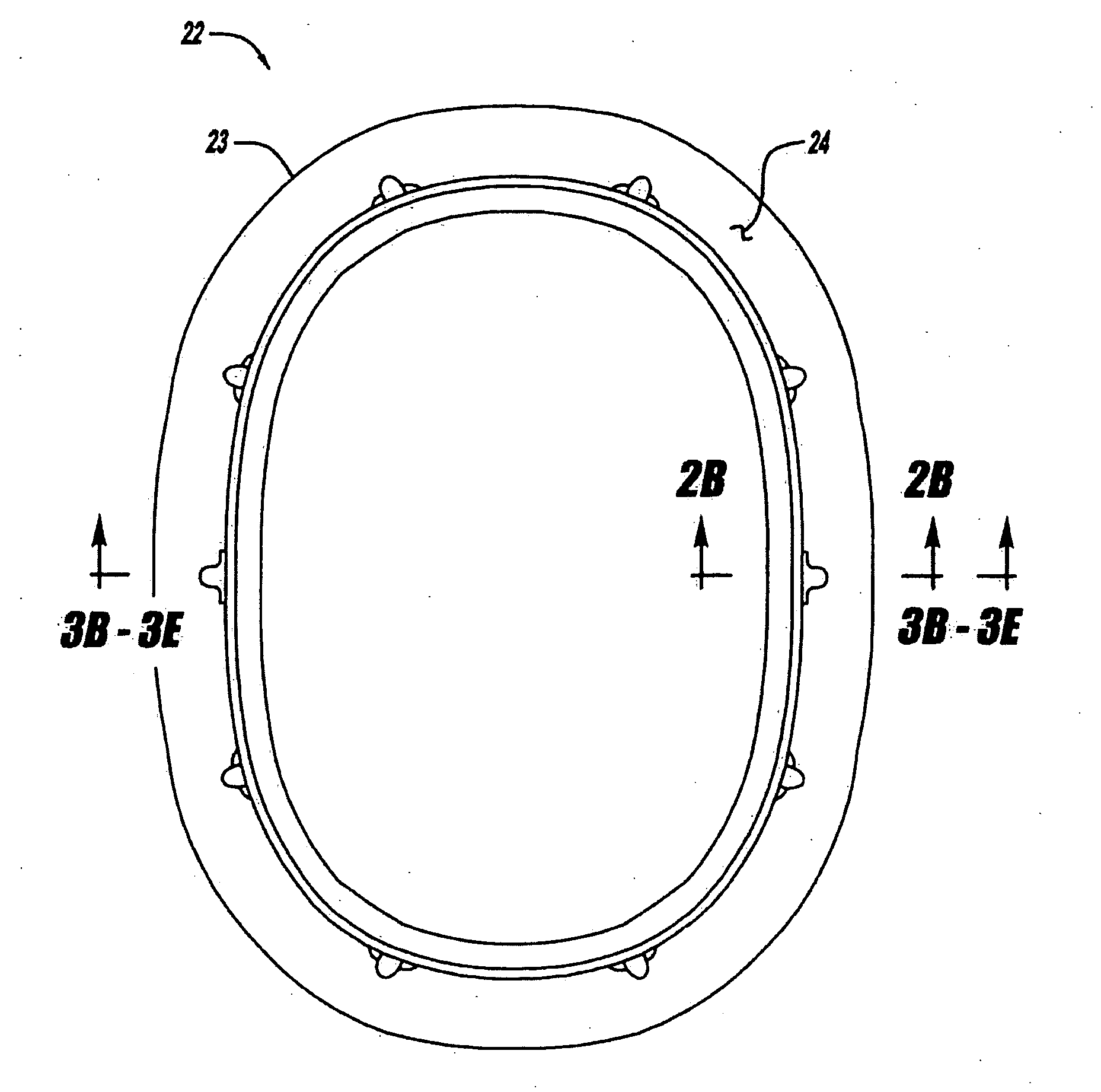
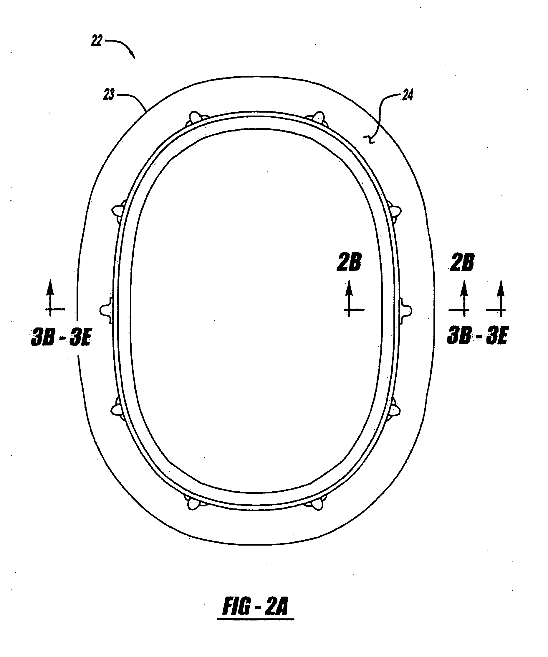
[0031] Another path of noise propagation, from the aircraft exterior 104 to the rubber seal 102 is noted by arrow 116. The rubber seal 102 lies within the c-ring 24. The flange 30 and web 32 provide support to the rubber seal 102, which helps secure the window layers 108, 110, 112. The advantage of the window 100 of the first embodiment over the baseline window of FIG. 3A, is that increased sound dampening is achieved, at least because of its thicker outer layer 112 and its greater edge amount that abuts against the rubber seal 102. By dampening or eliminating noise, passenger comfort inside the aircraft is increased. In the case of noise path 116 the noise may propagate through the outer layer 112, but will then be partially or completely dampened by the rubber seal 102.

[0032] Turning now to FIG. 3C, a second embodiment of the present invention will be explained. The window 120 of the second embodiment has an increased number of layers, from three to four, over the second embodimen...

fourth embodiment

[0040]FIG. 5 is a comparison graph that depicts the vibration reduction, in decibels (dB), achieved with the fourth embodiment window 160 having an outer pane of 0.22″ acrylic, 0.05″ visco-material, and 0.12″ glass. This particular window, known as the “visco-elastic window”, is depicted in FIG. 3E. The vibration reduction is calculated using the following formula:

Reduction (dB)=20 log(X2 / X1)

where X1 is the velocity PSD of the prior art window of FIG. 3A and X2 is the velocity PSD of the fourth embodiment window 160. Although the calculation was performed in terms of structural velocity, it is assumed that the normal velocity of the window is directly proportional to the radiated acoustic pressure. Therefore, the noise reduction associated with the fourth embodiment window is also represented by FIG. 5.

[0041] The results depicted in FIG. 5 are relative to the baseline window of FIG. 3A. As an example, the fourth embodiment visco-elastic window dampens 6 decibels more at 200 Hz tha...


PUM

PropertyMeasurementUnit
Weightaaaaaaaaaa
Forceaaaaaaaaaa
Viscosityaaaaaaaaaa

Abstract

An aircraft window configuration utilizes a laminate build-up of the primary pane to increase damping and reduce the structural response to the turbulent boundary layer outside the aircraft. The laminate may consist of several acrylic layers or a combination of acrylic and glass layers. Noise dampening results from the introduction of a transparent visco-elastic material or a urethane. A vacuum layer may be introduced between the primary pane and a middle, or fail-safe pane. The vacuum layer decouples the panes over a broad frequency range resulting in a lower response of the inner pane that radiates noise into the passenger cabin. Such a window configuration reduces weight and improves noise performance. A damped laminate also reduces pane deflections into the air stream and improves aerodynamic performance of the aircraft.

Description

FIELD OF THE INVENTION [0001] The present invention relates to an airborne mobile platform laminate window that reduces vibration and sound transmissions to the airborne mobile platform fuselage interior. BACKGROUND OF THE INVENTION [0002] The reduction of sound transmissions to the fuselage interior of an airborne mobile platform (e.g. a modern jet aircraft) is becoming more of a concern for commercial aircraft manufacturers and their customers in an increasingly-competitive international marketplace. Commercial aircraft manufacturers and their customers are interested in reducing the level of noise inside their aircraft. More specifically, they are interested in reducing the amount of noise that is transferred from the aircraft exterior to the aircraft interior. Noise is typically created by the turbulent flow along the fuselage and radiated from the engine exhaust plume. An area of the aircraft through which noise is typically transferred is the fuselage sidewall, including the a...

Claims


Application Information

Patent Timeline
IPC IPC(8): B64C1/14
CPCB64C1/1484B32B2333/12B32B17/10018B64C1/1492
Inventor RASSAIAN, MOSTAFALEE, JUNG-CHUANMONTGOMERY, JOSHUA M.PARE, SHAWN M.CHRISTENSON, TERRY N.
Owner THE BOEING CO
Why Eureka
Try Eureka