Touch-flow water supply apparatus

a technology of water supply apparatus and touch-flow, which is applied in the direction of mechanical equipment, valve housings, operating means/releasing devices of valves, etc., can solve the problems of inapplicability, sanitary problems, and the handle can be easily broken, so as to achieve convenient and practical control, convenient

Inactive Publication Date: 2007-03-29
LIN HUI HUANG
View PDF10 Cites 66 Cited by
  • Summary
  • Abstract
  • Description
  • Claims
  • Application Information

AI Technical Summary

Benefits of technology

[0009] 1. The preferred embodiment of the present invention primarily connects the touch sensory controller 30 to the structure of water supply apparatus, and an electronic control valve 20 is placed on the channel of the water supply apparatus, then design of the use touch sensory controller to control the switch of the electronic control valve and to turn the water apparatus on and for, so that the water supply apparatus is easy to control, and more convenient and more practical.

Problems solved by technology

Take the faucet of the conventional water supply apparatus for example, the water supply valve is usually a rotary knob or lever, because it needs a human hand to touch the handle and operate it with force, therefore, this structure creates sanitary problems in the public area, and the handle can be easily broken because someone may use it with improper force.
Based on this reason, even though some of the business has developed faucets that are electronic controlled with infrared sensor to supply and shut off water automatically, except, because of the module and time for water flow is fixed inflexibly, therefore, if it is applied to regular home environment, it may not be applicable because of its inflexibility.
Moreover, in terms of the water supply apparatus for the spray gun, the conventional spray gun usually supplies water by holding down the hand, in the process as such, people's hand must hold down the handle for a long time, therefore, it creates disadvantage such as inconvenience in operating.

Method used


Image

  • Touch-flow water supply apparatus
  • Touch-flow water supply apparatus
  • Touch-flow water supply apparatus

Examples


Embodiment Construction

[0021] The features and the advantages of the present invention will be more readily understood upon a thoughtful deliberation of the following detailed description of a preferred embodiment of the present invention with reference to the accompanying drawings.

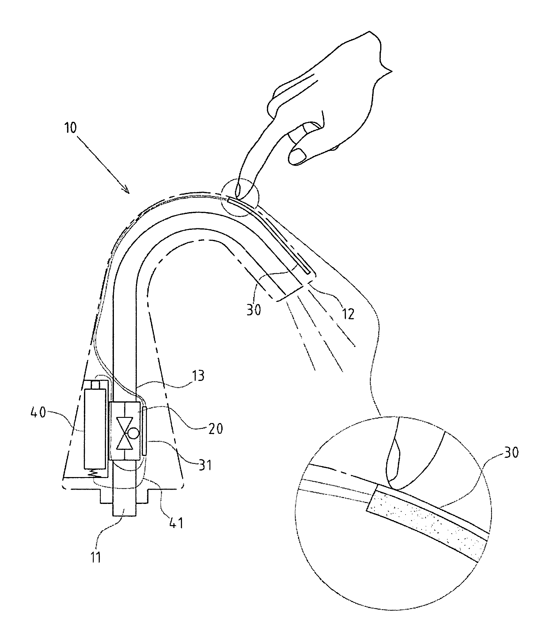
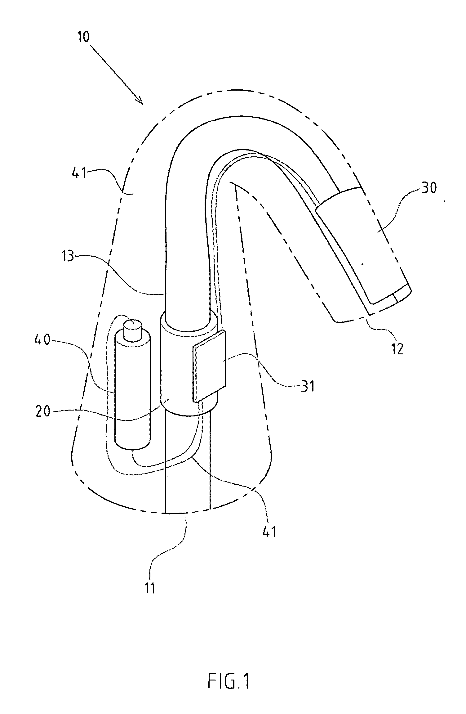
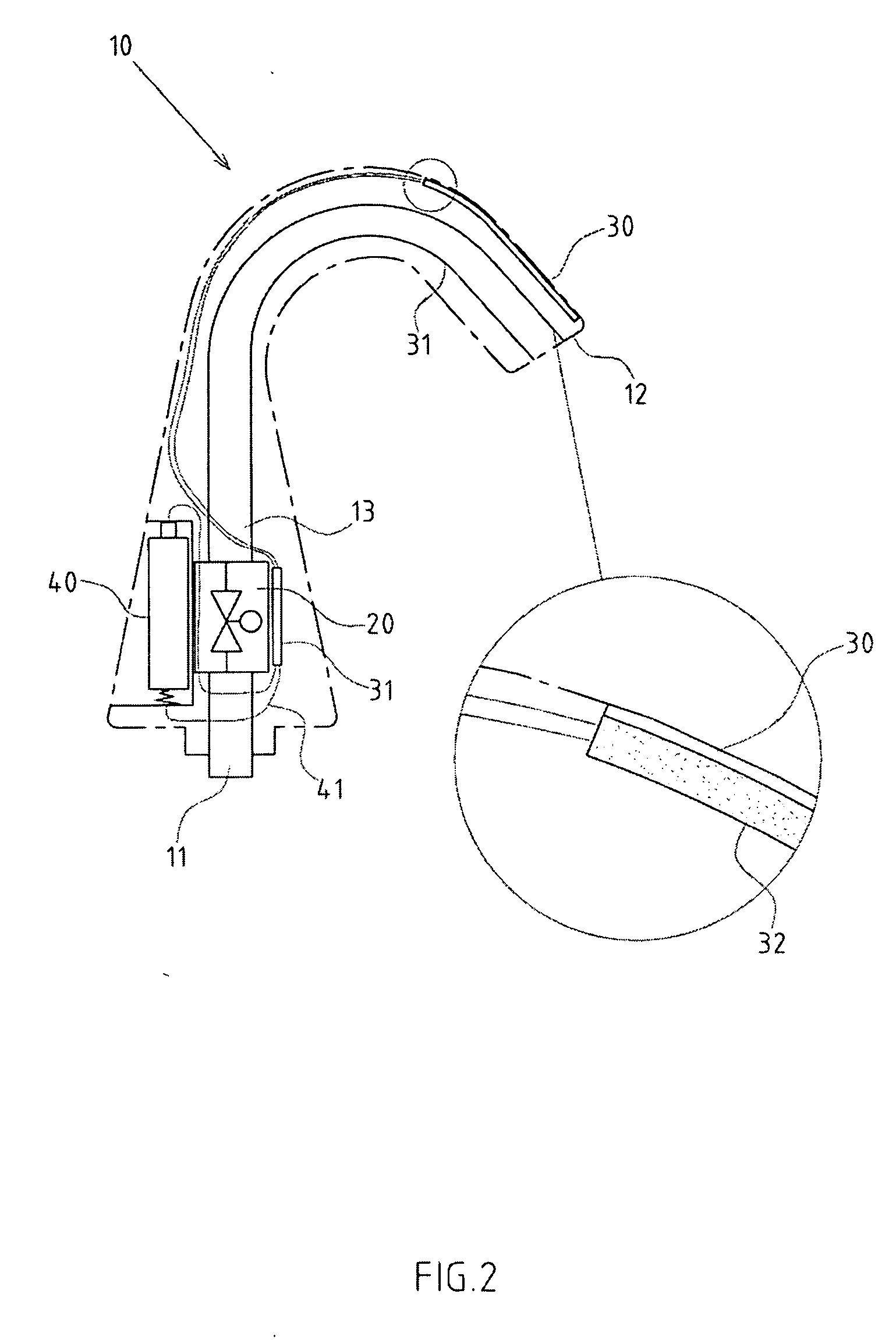
[0022] As shown in FIGS. 1-2, there is a preferred embodiment of the touch-flow water supply apparatus.

[0023] The invention includes a water supply apparatus 10, the water supply apparatus of the embodiment being a faucet, which includes a water inlet 11 and a water outlet 12.

[0024] There is an electronic control valve 20, which can be electronic-magnetic valve, it can be placed on the channel 13 between the water inlet and outlet 1112 of the water supply apparatus.

[0025] The invention also includes a touch sensory controller 30, which can be placed on the water supply apparatus 10 for people's hands to touch and operate.

[0026] A circuit controller 31 connects the electronic control valve 20 and touch sensory controller 30...


PUM


Abstract

The present invention is a water supply apparatus. A conventional water supply apparatus is mostly based on rotary and lever, which creates inconvenience. Also, there is a problem like inability to control the time of water supply. The primary features of the apparatus are connecting the touch sensory controller to the water supply apparatus, and the channel of the water supply apparatus having an electronic control valve, using the touch sensory controller to control the electronic control valve by circuit controller, and switch the water supply apparatus. The power electronic control valve needed may be supplied by the set of battery on the water supply apparatus or using external power. The operation and control of the water supply apparatus is more convenient and practical.

Description

RELATED U.S. APPLICATIONS [0001] Not applicable. STATEMENT REGARDING FEDERALLY SPONSORED RESEARCH OR DEVELOPMENT [0002] Not applicable. REFERENCE TO MICROFICHE APPENDIX [0003] Not applicable. FIELD OF THE INVENTION [0004] The present invention relates generally to a water supply apparatus, and more particularly to a design that supplies water with a touch-flow water supply apparatus. BACKGROUND OF THE INVENTION [0005] Take the faucet of the conventional water supply apparatus for example, the water supply valve is usually a rotary knob or lever, because it needs a human hand to touch the handle and operate it with force, therefore, this structure creates sanitary problems in the public area, and the handle can be easily broken because someone may use it with improper force. Based on this reason, even though some of the business has developed faucets that are electronic controlled with infrared sensor to supply and shut off water automatically, except, because of the module and time ...

Claims


Application Information

Patent Timeline
Patent Type & Authority Applications(United States)
IPC IPC(8): F16K31/02
CPCE03C1/0404E03C1/055F16K31/02F16K11/24F16K27/06E03C1/08
Inventor LIN, HUI-HUANG
Owner LIN HUI HUANG
Why Eureka
Try Eureka