Wheel Rim with Hollow Flanges for Mounting of a Tire

Inactive Publication Date: 2007-03-29
ALEX GLOBAL TECH
View PDF13 Cites 3 Cited by
  • Summary
  • Abstract
  • Description
  • Claims
  • Application Information

AI Technical Summary

Benefits of technology

[0008] An object of this invention is to provide a wheel rim that has a structura

Problems solved by technology

However, this results in an increas

Method used


Image

  • Wheel Rim with Hollow Flanges for Mounting of a Tire
  • Wheel Rim with Hollow Flanges for Mounting of a Tire
  • Wheel Rim with Hollow Flanges for Mounting of a Tire

Examples


Embodiment Construction

[0023] Before the present invention is described in greater detail in connection with the preferred embodiments, it should be noted that similar elements and structures are designated by like reference numerals throughout the entire disclosure.

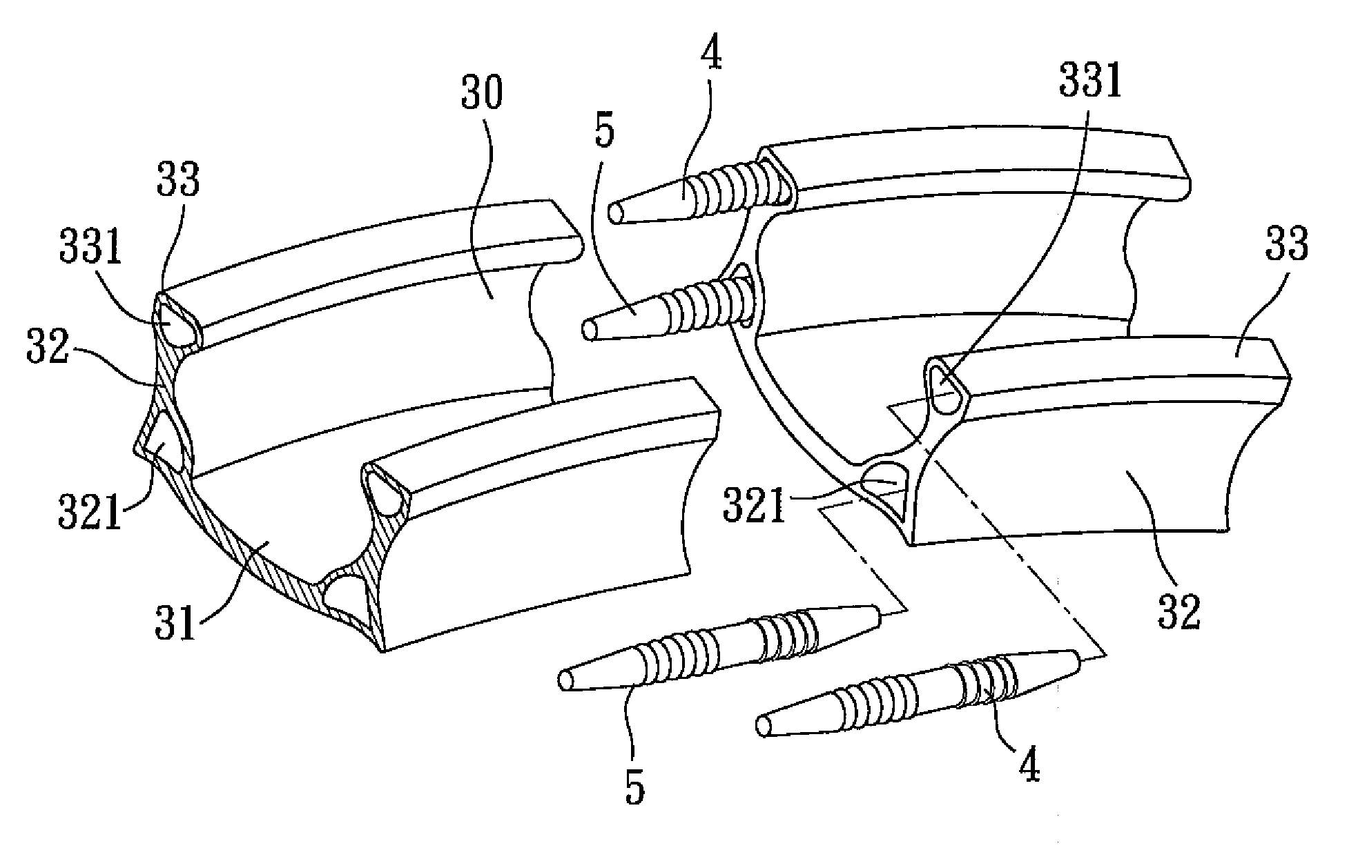
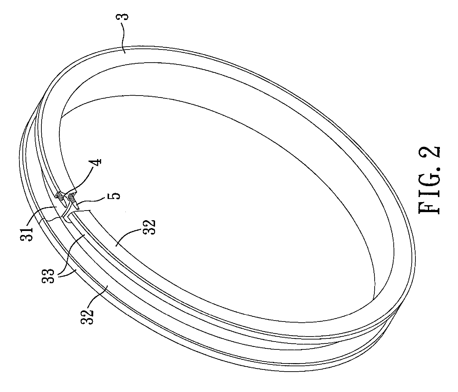
[0024] Referring to FIGS. 2 and 3, the first preferred embodiment of a bicycle wheel rim according to this invention is adapted for mounting of a tire (not shown) thereon. The wheel rim includes an annular frame 3 having two end surfaces abutting against each other in a known manner, two first engaging rods 4, and two second engaging rods 5. Each of the first and second engaging rods 4, 5 is inserted into the end surfaces.

[0025] The annular frame 3 includes an annular bottom wall 31, a pair of annular left and right sidewalls 32 extending respectively, radially, and outwardly from left and right sides of the bottom wall 31, and two annular flanges 33 extending respectively and axially from radial outer ends of the left and right sidewalls 32...


PUM


Abstract

A wheel rim is adapted for mounting of a tire thereon, and comprises an annular frame. The annular frame includes two end surfaces abutting against each other, an annular bottom wall, and a pair of annular left and right sidewalls extending respectively, radially, and outwardly from left and right sides of the bottom wall. Two annular flanges extend respectively and axially from radial outer ends of the left and right sidewalls toward each other. Each of the flanges is formed with a first through hole that extends from one of the end surfaces to the other of the end surfaces.

Description

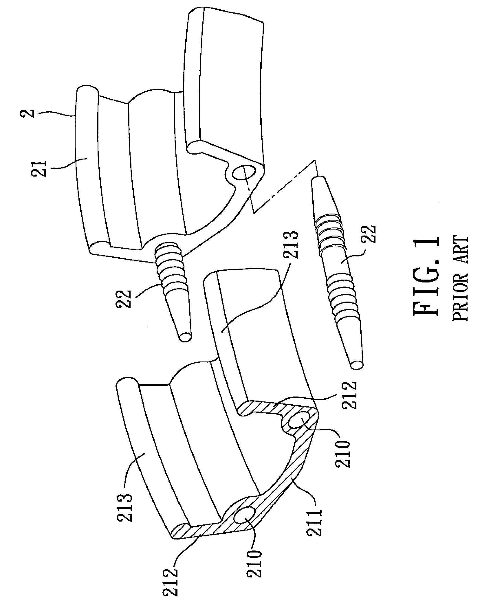
CROSS-REFERENCE TO RELATED APPLICATION [0001] This application claims priority of Taiwanese Application No. 094133364, filed on Sep. 26, 2005. BACKGROUND OF THE INVENTION [0002] 1. Field of the Invention [0003] This invention relates to a wheel rim, and more particularly to a wheel rim that is formed with hollow rim flanges. [0004] 2. Description of the Related Art [0005] Referring to FIG. 1, a conventional bicycle wheel rim 2 includes an annular frame 21, and two engaging rods 22 each inserted into two end surfaces of the annular frame 21. The annular frame 21 includes an annular bottom wall 211, and two annular sidewalls 212 extending respectively and radially from left and right sides of the bottom wall 211 for mounting of a tire (not shown) thereon. A radial inner end of each of the sidewalls 212 has a through hole 210 formed therethrough and extending along a circumferential direction thereof for insertion of the corresponding engaging rod 22. [0006] Designs of wheel rims focus...

Claims


Application Information

Patent Timeline
IPC IPC(8): B60B21/02
CPCB60B21/00
Inventor CHEN, CHAO-YING
Owner ALEX GLOBAL TECH
Why Eureka
Try Eureka