
Method and system for reducing the appearance of jaggies when deinterlacing moving edges

a technology of moving edges and reducing the appearance of jaggies, which is applied in the field of video processing, can solve the problems of affecting the viewing experience, affecting the motion of objects in images, and causing visual artifacts to become more prominent,

Inactive Publication Date: 2007-03-29
AVAGO TECH WIRELESS IP SINGAPORE PTE
View PDF2 Cites 20 Cited by
  • Summary
  • Abstract
  • Description
  • Claims
  • Application Information

AI Technical Summary

Benefits of technology

[0036]FIG. 20 illustrates an exemplary structure of the low angle p

Problems solved by technology

In video compression, communication, decompression, and display, there has been for many years problems associated with supporting both interlaced content and interlaced displays along with progressive content and progressive displays.
Certain problems may arise concerning the motion of objects from image to image during deinterlacing.
However, visual artifacts become more pronounced with video images containing a lot of motion and change from one image to another, when converted from interlaced to progressive video format.
An incorrect decision of motion in a video image results in annoying visual artifacts in the progressive output thereby providing an unpleasant viewing experience.
Several designs have attempted to find a solution for this problem but storage and processing constraints limit the amount of spatial and temporal video information that may be used for motion detection.
During deinterlacing, moving edges, especially edges of low-angle (near-horizontal edges), can produce an annoying artifact of the appearance of “jaggies.” Previous systems did not provide a good solution of detecting and correcting jaggies.
Some angle detectors are capable of handling edges with relatively steep angles (near-vertical) but for those angles that are closer to horizontal, many detectors fail to “see” the angled edge which results in the jaggy artifacts.

Method used


Image

  • Method and system for reducing the appearance of jaggies when deinterlacing moving edges
  • Method and system for reducing the appearance of jaggies when deinterlacing moving edges
  • Method and system for reducing the appearance of jaggies when deinterlacing moving edges

Examples


Embodiment Construction

[0037] Certain embodiments of the present invention relate to processing video. More specifically, certain embodiments of the invention relate to a method and system for reducing the appearance of jaggies when deinterlacing moving edges. While the following discusses detecting a direction of an edge at a low-angle, it should be understood that an embodiment of the present invention may detect all angles, including low angles.

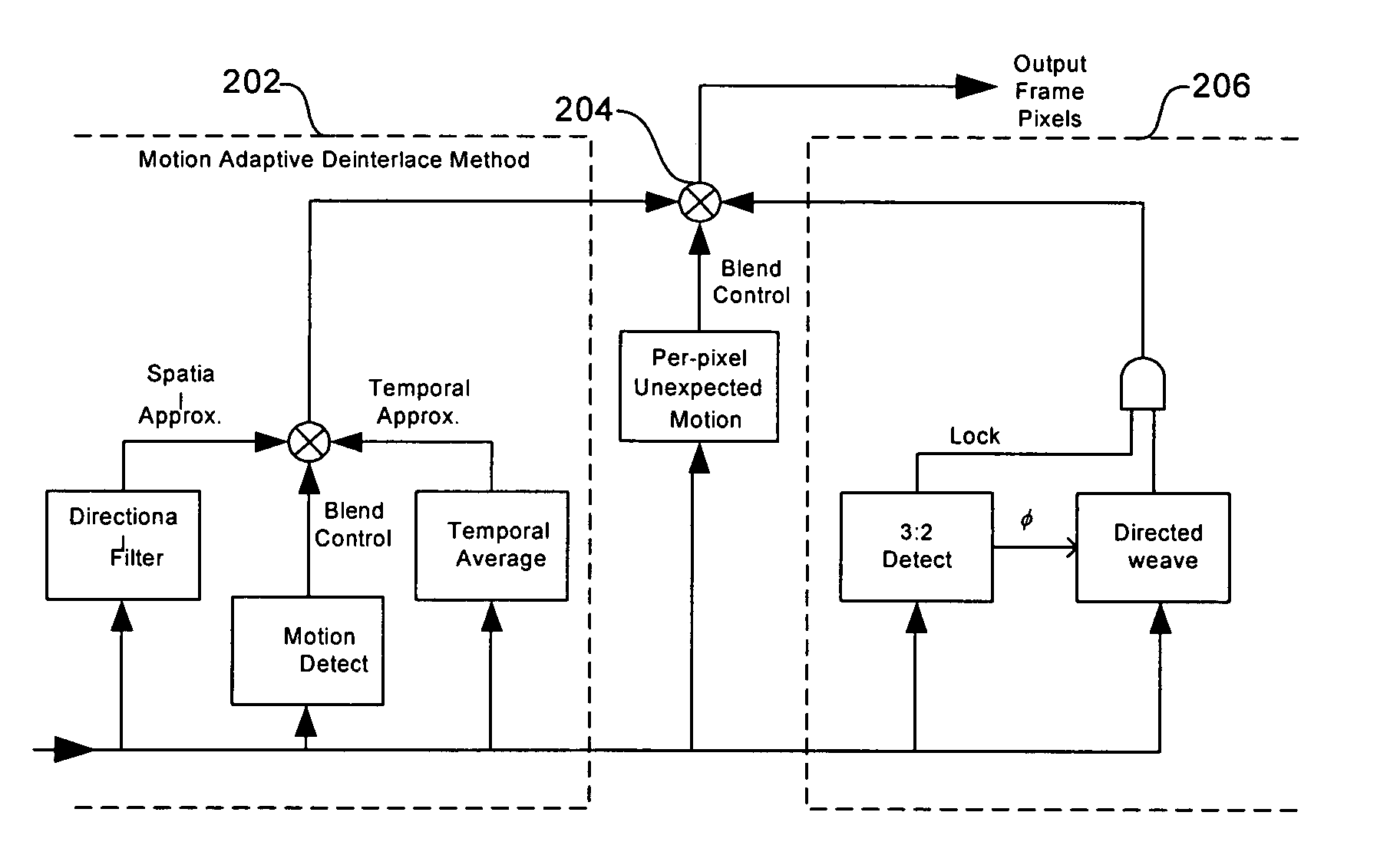
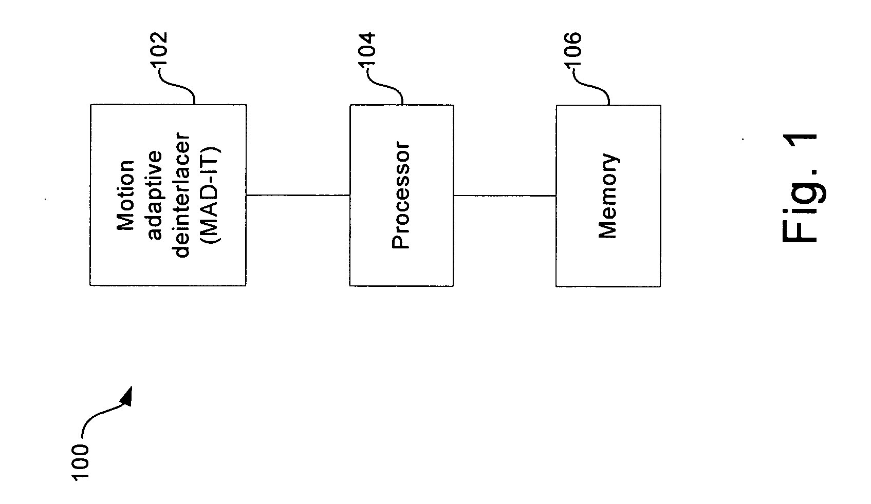
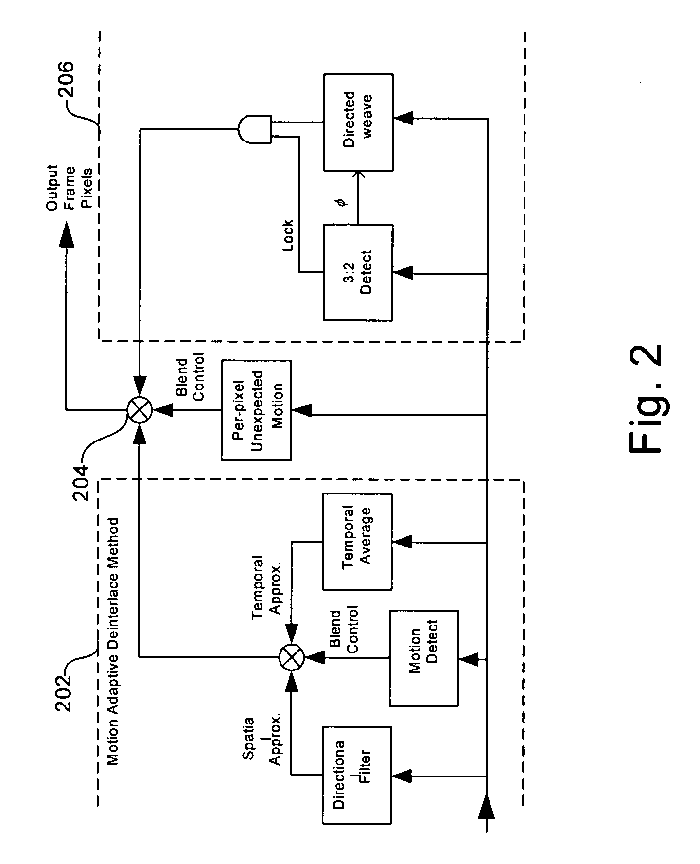
[0038]FIG. 1 illustrates a block diagram of an exemplary architecture for positioning of a motion adaptive deinterlacer, in accordance with an embodiment of the present invention. Referring to FIG. 1, the deinterlacer system 100 may comprise a motion adaptive deinterlacer with inverse telecine (MAD-IT) 102, a processor 104, and a memory 106. The MAD-IT 102 may comprise suitable logic, code, and / or circuitry that may be adapted to deinterlace video fields. The processor 104 may comprise suitable logic, code, and / or circuitry that may be adapted to control the op...


PUM


Abstract

A method and system for reducing the appearance of jaggies when deinterlacing moving edges in a video processing system are provided. The method may comprise detecting the direction of an angled edge in an interlaced video image to determine a filtering direction to be used for approximating absent pixels in deinterlacing the interlaced video. In detecting the direction of the angled edge, a group of windows of different sizes may be used to look at the edge, where a missing pixel is the center of each of the windows. Detecting the direction of the edge, and therefore the direction of filtering, may comprise: determining the angle associated with the edge, determining the strength of the edge, examining the pixels surrounding the absent pixel, and adjusting the first angle measure and the second angle measure based on the pattern of the surrounding pixels.

Description

RELATED APPLICATIONS [0001] The application makes reference to, claims priority to, and claims the benefit of U.S. Provisional Application Serial No. 60 / 720,021 filed on Sep. 23, 2005, which is hereby incorporated herein by reference in its entirety.FEDERALLY SPONSORED RESEARCH OR DEVELOPMENT [0002] Not Applicable MICROFICHE / COPYRIGHT REFERENCE [0003] Not Applicable FIELD OF THE INVENTION [0004] Certain embodiments of the present invention relate to processing video. More specifically, certain embodiments of the invention relate to a method and system for reducing the appearance of jaggies when deinterlacing moving edges. BACKGROUND OF THE INVENTION [0005] In video system applications, a picture is displayed on a television or a computer screen by scanning an electrical signal horizontally across the screen one line at a time using a scanning circuit. The amplitude of the signal at any one point on the line represents the brightness level at that point on the screen. When a horizont...

Claims


Application Information

Patent Timeline
IPC IPC(8): H04N11/20
CPCH04N5/142H04N7/012H04N5/144
Inventor WYMAN, RICHARD H.SCHONER, BRIAN
Owner AVAGO TECH WIRELESS IP SINGAPORE PTE
Learn More