
Image processing apparatus and image processing method

a technology of image processing and image processing, applied in the field of image processing system, can solve the problems of limited screen resolution, various conventional systems, and inability to remove jaggies based on pattern matching

Active Publication Date: 2005-04-21
CANON KK
View PDF2 Cites 11 Cited by
  • Summary
  • Abstract
  • Description
  • Claims
  • Application Information

AI Technical Summary

Benefits of technology

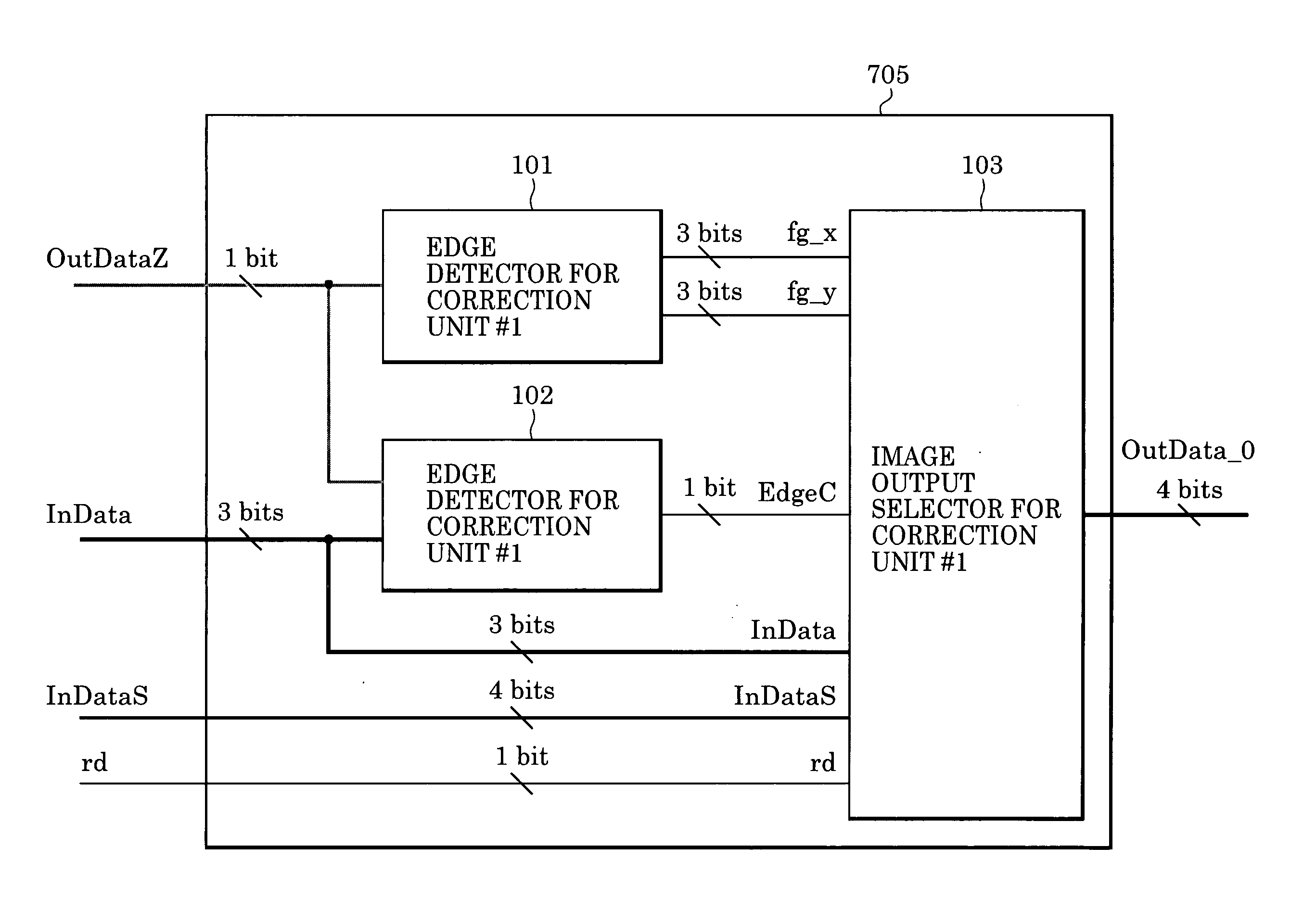
[0029] In an aspect, the present invention provides an image processing system comprising an input unit for inputting N-bit multilevel image data, a pseudo halftone representation unit for converting the N-bit image data into M-bit image data, a first bit conversion unit for converting the N-bit image data into L-bit image data, a control signal generation unit for generating a control signal from the L-bit image data, a first edge detection unit for detecting a first edge from the control signal generated by the control signal generation unit, a second edge detection unit for detecting a second edge different from the first edge from the c...

Problems solved by technology

However, generally, conventional systems have various disadvantages as described below with reference to FIGS. 23A and 23B.
In this case, smoothing based on pattern matching cannot remove the jaggies.
The screen resolution is limited to the above described range because higher screen resolutions do not lead to high quality in images formed by electrophotographic printers.
When an image compressed by means of lossy compression such as JPEG compression is subjected to smoothing process, mosquito noise (that occurs in an image with high-frequency components or occurs at edges of an image when the data size is compressed by a large factor by means of lossy compression) can occur due to degradation caused by the compression.
If such a failure occurs in the matching process, good smoothing cannot be achieved.
Although the '141 patent attempts to address some of the above disadvantages, it has been found that many conventional image processing systems are unable to provide suitable smoothing for both multilevel images and for images based on processes other than error diffusion process.

Method used


Image

  • Image processing apparatus and image processing method
  • Image processing apparatus and image processing method
  • Image processing apparatus and image processing method

Examples


Embodiment Construction

[0058] The present invention is described in further detail below with reference to embodiments in conjunction with the drawings.

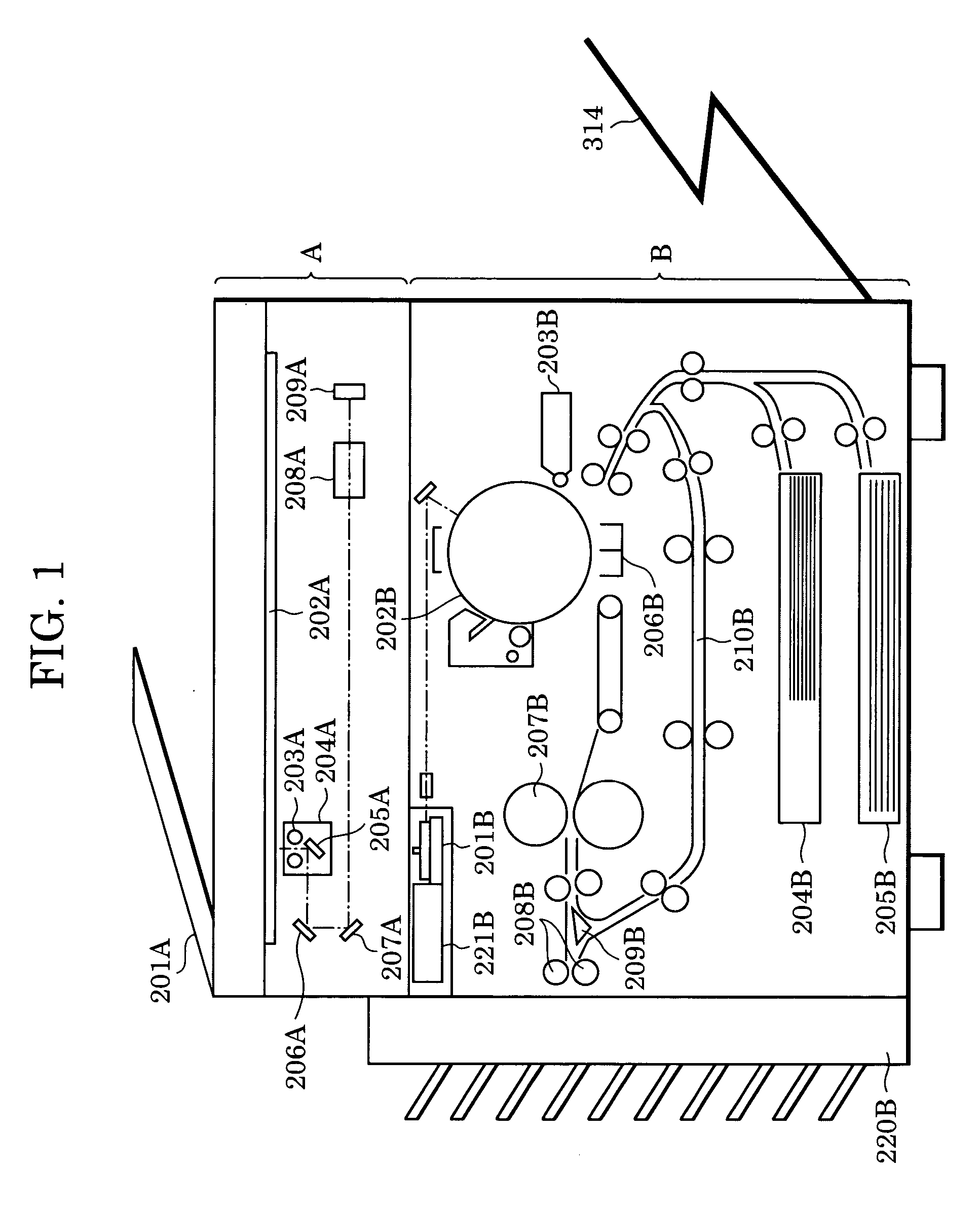
[0059]FIG. 1 is a cross-sectional view schematically showing a multifunction peripheral system using an image processing system according to the present invention. This multifunction peripheral system includes, as mechanical parts, a color scanner A and a printer B.

[0060] In a color scanner unit A shown in FIG. 1, a document feeder 201A feeds documents one by one from a last page onto platen glass 202A. After scanning is completed, the document feeder 201A removes the document from the platen glass 202A. When a document is put on the platen glass 202A, a lamp 203A is lit, and a scanner unit 204A on which the lamp 203A is disposed is moved so as to expose the document with light while scanning the document. During the scanning operation, reflected light from the document is directed to a CCD color image sensor (hereinafter, referred to simply as “CCD”) 20...


PUM


Abstract

A smoothing process is performed on image data to obtain improved image quality. Output image data is switched among image data subjected to smoothing, image data subjected to second bit conversion, and image data subjected to pseudo halftone representation process. In this manner, jaggies at edges can be smoothed even in multilevel image data subjected to image forming process such as screen processing. Smoothing for image data with degraded image quality due to, for example, lossy compression such as JPEG compression can also be achieved. Furthermore, degradation in image quality that occurs when a conventional smoothing process is applied to image data subjected to particular image processing can be avoided.

Description

[0001] This application claims priority from Japanese Patent Application No. 2003-360286 filed Oct. 21, 2003, which is hereby incorporated by reference herein. BACKGROUND OF THE INVENTION [0002] 1. Field of the Invention [0003] The present invention relates to an image processing system capable of correcting image imperfections to increase image quality. [0004] 2. Description of the Related Art [0005] In the art of image processing system, several techniques are known to improve jaggies that occur on images printed with printers with a low resolution. [0006] Jaggies are jagged edges around printed characters, that is, they are stairstep-like irregularities that appear at edges of characters. An example is shown in FIG. 21. [0007]FIG. 21 is a schematic diagram showing a manner in which a character is processed by a conventional image processing system. In the example shown in FIG. 21, jaggies occur at edges of the character. [0008] In FIG. 21, each of small blocks arranged in a matri...

Claims


Application Information

Patent Timeline
IPC IPC(8): G06T5/00H04N1/405H04N1/409B41J2/52
CPCH04N1/4092G06T7/0085G06T5/20G06T5/002G06T7/13G06T5/70
Inventor KABURAGI, HIROSHI
Owner CANON KK
Learn More