Electrical load status detection and control device

a technology of load status detection and control device, which is applied in the direction of relays, emergency protective arrangements for limiting excess voltage/current, manufacturing tools, etc., can solve the problems of lack of effective protection device, and achieve the effect of reducing power waste and ensuring electric use safety

Inactive Publication Date: 2007-03-29
PRODIGIT ELECTRONICS
View PDF1 Cites 60 Cited by
  • Summary
  • Abstract
  • Description
  • Claims
  • Application Information

AI Technical Summary

Benefits of technology

[0010] Comparing with the conventional power supply control devices, through the control performance of the no-load status detection unit and the load status detection unit of the

Problems solved by technology

Among all the existing power supplying systems or devices, most of which are lacking of proper protecting device to effective

Method used


Image

  • Electrical load status detection and control device
  • Electrical load status detection and control device
  • Electrical load status detection and control device

Examples


Embodiment Construction

[0014] The elements, circuits, devices, characteristics and the best embodiment of this invention are described with relative figures as follows.

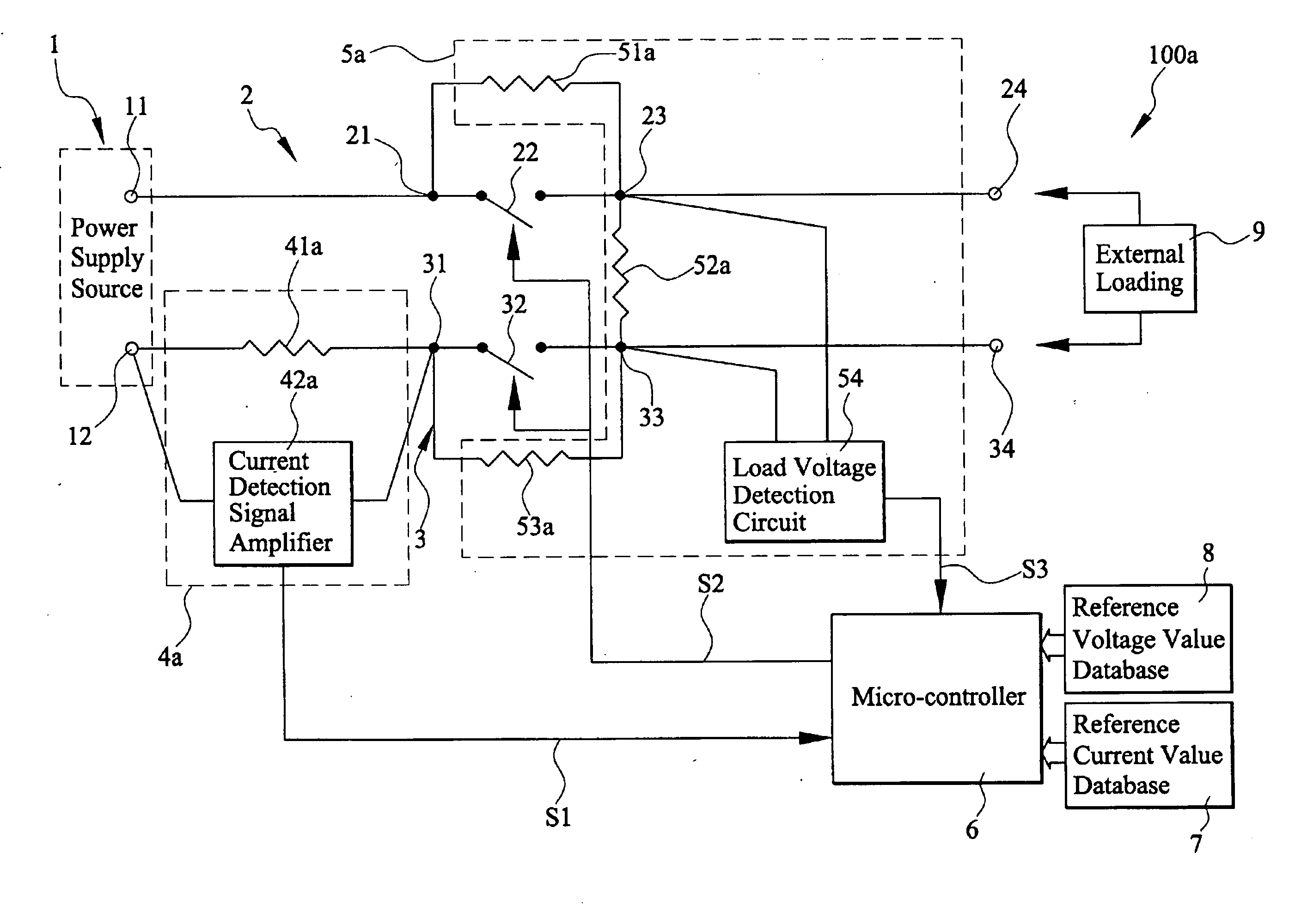
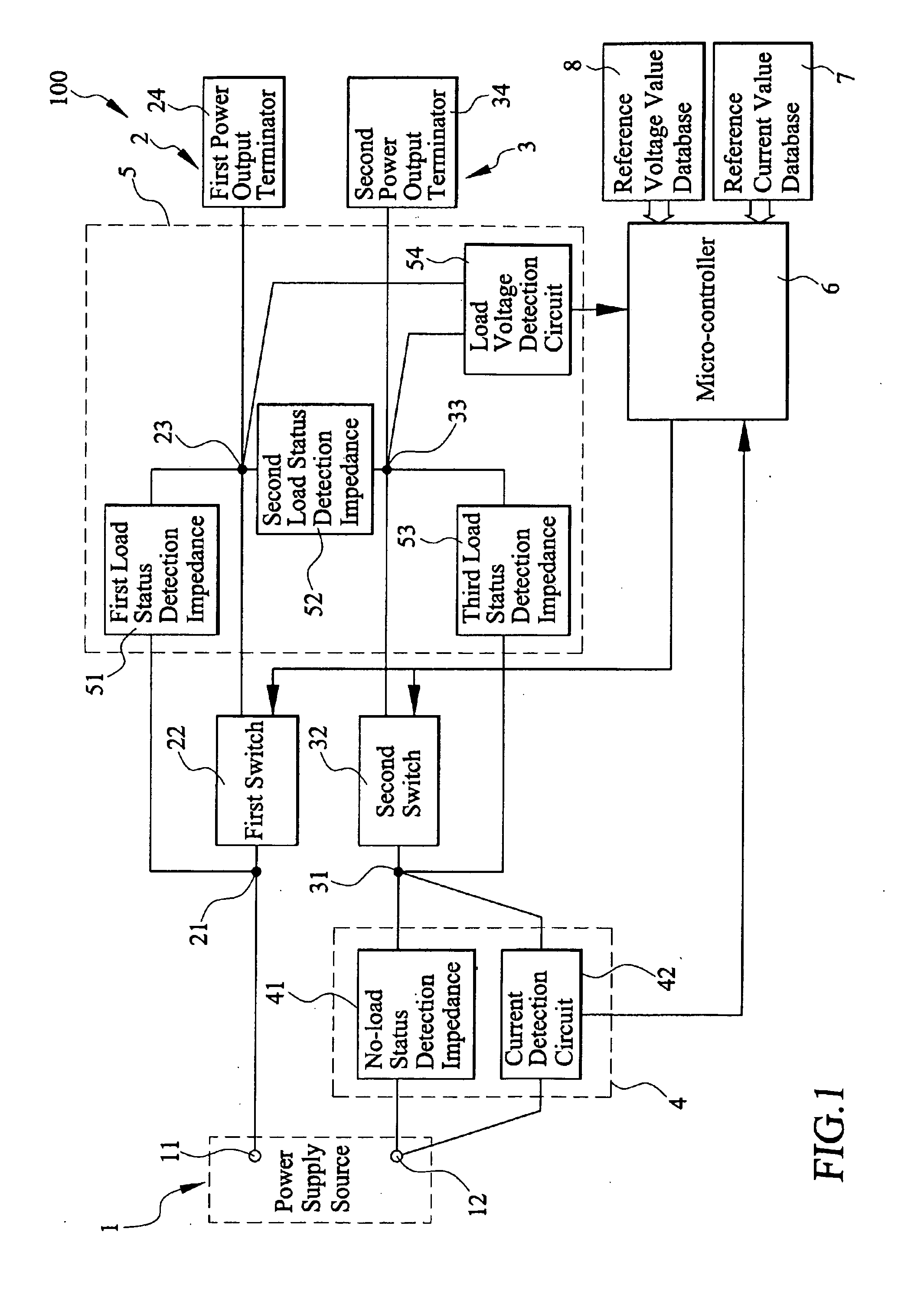
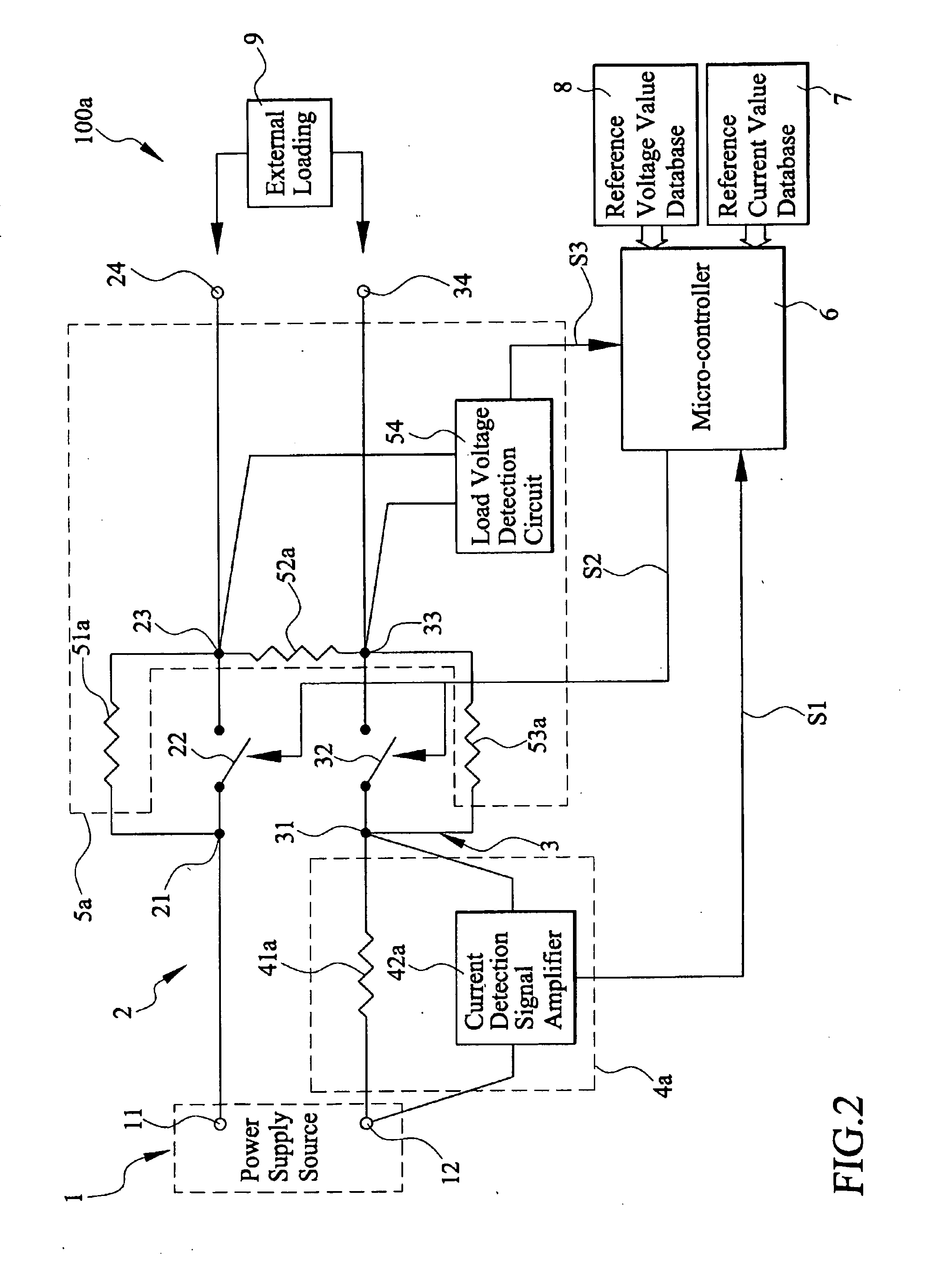
[0015] Please refer to FIG. 1, which presents arrangement relation of a device in accordance with a best embodiment of the invention. An electrical load status detection and control device 100 for automatically detecting and switching power supplying between a loading status and a no-load status is connected with a power supply source 1 and provided with a first power supply terminator 11 and a second power supply terminator 12. The electrical load status detection and control device 100 includes a first power supply circuit loop 2, a second power supply circuit loop 3, a no-load status detection unit 4, a load status detection unit 5, a micro-controller 6, a reference current value database 7, and a reference voltage value database 8.

[0016] The first power supply circuit loop 2 includes a first node 21, a first switch 22, a second node 2...


PUM

PropertyMeasurementUnit
Electrical resistanceaaaaaaaaaa
Currentaaaaaaaaaa
Electric potential / voltageaaaaaaaaaa

Abstract

An electrical load status detection and control device includes a first power supply circuit loop with a first switch, a second power supply circuit loop with a second switch, a no-load status detection unit connected with the second power supply circuit loop for detecting the current passing through the second power supply circuit loop and thereby generating a current detection signal. A micro-controller connected with a reference current value database, the no-load status detection unit, the first switch and the second switch, which receives the current detection signal from the no-load status detection unit. The micro-controller generates a switching signal to actuate the first switch and the second switch to thereby open the first power supply circuit loop and the second power supply circuit loop when detecting the current passing through the second power supply circuit loop out of the reference current value range of the reference current value database.

Description

FIELD OF THE INVENTION [0001] The present invention relates to a power supply control device, and more particularly to an electrical load status detection and control device. BACKGROUND OF THE INVENTION [0002] Nowadays, the cost of energy generation rises higher and higher with the continuous increase of the international crude oil price. Thus, most people, governments, and environment protecting organization all over the world are advocating the policy of economizing on the use of energy. Especially, with the factors of warmer climate and denser population distribution, the total consumption of energy for both industrial and civil use has grown up day after day. Under this condition, to utilize energy in effective ways has become one of the most important problems to be solved right now. [0003] Nevertheless, among all existed power supplying systems or devices, the phenomenon of electric leakage under the no-load situation exists almost unavoidably with the general ignorance of the...

Claims


Application Information

Patent Timeline
IPC IPC(8): H02H7/00
CPCH02H3/12
Inventor LIU, DANIEL
Owner PRODIGIT ELECTRONICS
Why Eureka
Try Eureka