Disposable modular hearing aid

a hearing aid and modular technology, applied in the field of disassembly and assembly of hearing aids, can solve the problems of loss of advantages of disposable hearing aids, design conflict of earmolds, etc., and achieve the effects of high degree of comfort, high degree of cleanliness, and replacemen

Inactive Publication Date: 2007-03-29
LEEDOM MARVIN A +8
View PDF42 Cites 74 Cited by
  • Summary
  • Abstract
  • Description
  • Claims
  • Application Information

AI Technical Summary

Benefits of technology

[0010] One possible solution to the conflict between comfort and durability of the earmold is the creation of a disposable hearing aid which uses ultra soft earmold materials that may not last over a four year period, but can be mass produced in an economically competitive manner. The earmold can therefore be replaced more frequently than the disposable hearing aid. An earmold that is replaced on a more frequent basis than the replacement cycle of the disposable aid can provide a user with benefits. If the earmold is replaced on a daily basis, as compared to a base unit which is replaced after a much longer period of time than the earmold, the user can be provided with a high degree of comfort, cleanliness, and performance.

Problems solved by technology

A design conflict for the earmold can then exist between the need to have a soft, pliant, nonirritating and comfortable material, and the need to have a durable material to protect the internal electronic components which can last more than four years.
If the battery can be replaced, the hearing aid is no longer disposable and the advantages of the disposable aid are lost.
“One-size-fits-all” type hearing aids generally lack a flexibility of their tips.
Such a lack of flexibility prevents deep penetration into the bony region of an ear canal by the hearing aid.
Such hearing aids are also unable to create an acoustic seal in the ear canal.
Also, hearing aids lacking a proper acoustic seal are prone to feedback.
Feedback is a nagging, unsolved problem for hearing aid manufacturers and dispensers.
While electrical feedback is more easily controllable with additional circuitry, the latter two forms of feedback in hearing aids remain significant problems that often reduce the effectiveness of hearing aid fittings.
Acoustical or mechanical feedback signals from the hearing aid receiver may be transduced by the hearing aid microphone, amplified in the circuitry and output from the receiver again but with higher gain, creating a feedback loop, and potentially oscillation.
Unfortunately, hearing aids frequently have feedback oscillation frequencies in the very range at which the wearer requires amplification most, such as in the frequency range between 1500 and 5000 Hz.
This process does not lend itself to high volume production.
The use of the port, however, can increase the acoustical feedback between the receiver and the microphone.
The feedback can lead to oscillations within the hearing aid at relatively low gain levels, compared to hearing aids without a pressure equalization port.

Method used


Image

  • Disposable modular hearing aid
  • Disposable modular hearing aid
  • Disposable modular hearing aid

Examples


Embodiment Construction

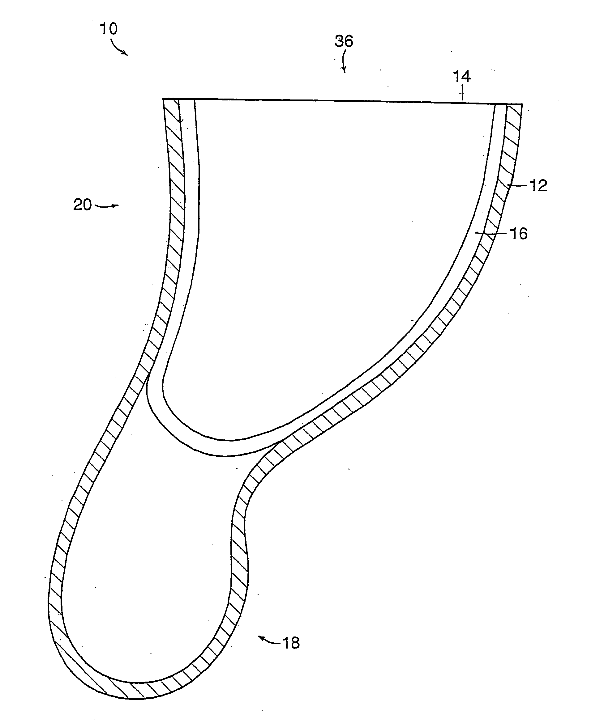
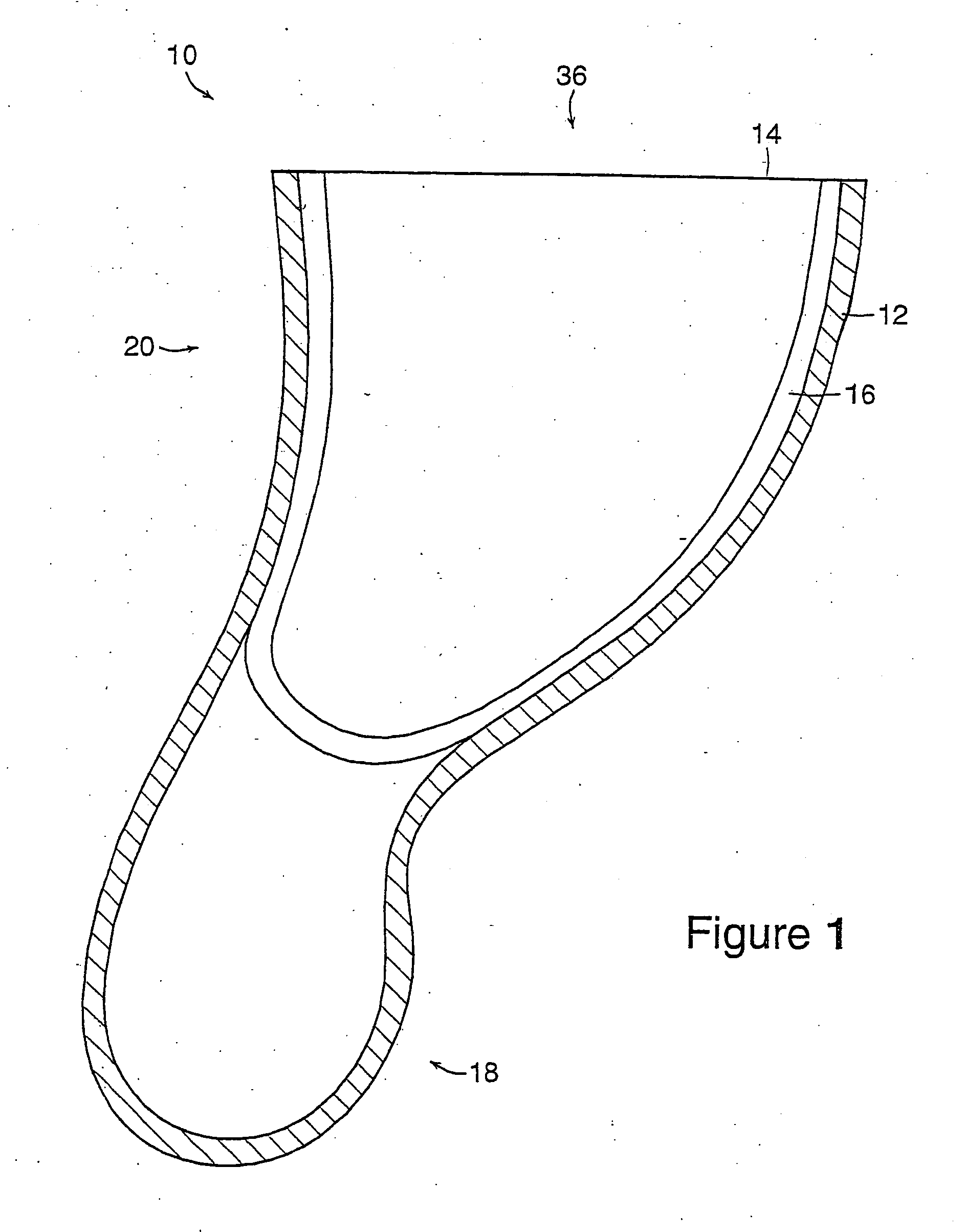
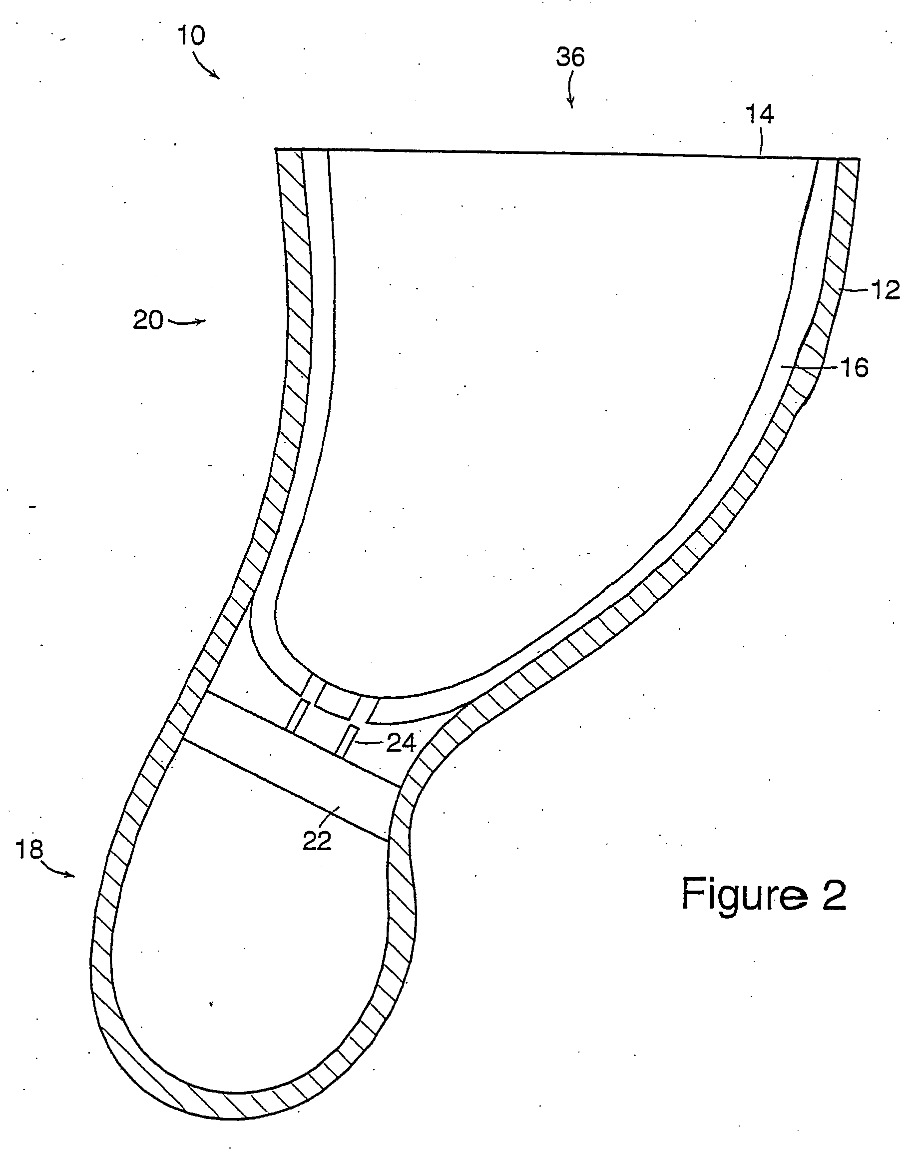
[0076] An embodiment of a modular hearing aid 10 is shown in FIG. 1. The modular hearing aid 10 can have an earmold 12 and a base unit 36. The base unit 36 can be a rigid or semi-rigid structure to which the earmold is attached or which holds and aligns other internal components. In one embodiment, the base unit 36 can be a core 14 having a shell 16. In a preferred embodiment both the earmold 12 and the base unit 36 can be replaced by the user after use. The earmold 12 can be replaced on a more frequent basis than the base unit 36.

[0077] The earmold 12 can have three preferred embodiments in any given embodiment of the modular hearing aid 10. In one embodiment, the earmold 12 forms an earmold tip 18. The earmold tip 18 can be made from an ultra soft and compliant material. The material can be an injection moldable, biocompatible thermoelastomer, such as C-flex (Consolidated Polymer Technologies, Inc., Largo, Fla.). The material, in a preferred embodiment, can be a castable, biocomp...


PUM


Abstract

A hearing aid includes a first half shell and a second shell attached to the first shell. A microphone, battery, electronics, a receiver and a flexible tip are mounted within a housing formed by the first half shell and the second half shell. A mechanical securing mechanism, located on the first half shell and the second half shell, attaches the first half shell to the second half shell. A flexible tip for a hearing aid includes a tip portion, a sound port attached to the tip portion and a vent formed in the flexible tip. The vent provides static pressure equilibrium between an ear canal and an ambient pressure.

Description

RELATED APPLICATIONS [0001] This application is a continuation of U.S. application Ser. No. 09 / 804,978, filed Mar. 13, 2001, which is a continuation-in-part of U.S. application Ser. No. 09 / 524,666, filed Mar. 13, 2000, which claims the benefit of U.S. Provisional Application No. 60 / 132,593, filed May 5, 1999 and claims the benefit of U.S. Provisional Application No. 60 / 157,873, filed Oct. 6, 1999. U.S. application Ser. No. 09 / 804,978, filed Mar. 13, 2001 also claims the benefit of U.S. application Ser. No. 09 / 524,501, filed Mar. 13, 2000, now U.S. Pat. No. 7,010,137, issued Mar. 7, 2006. The entire teachings of the above applications are incorporated herein by reference. [0002] This application is related to copending U.S. applications: ATTORNEYAPPLICATIONDOCKET NO.NO.TITLE2506.1005-00109 / 524,043Mass Produced Hearing AidWith a Limited Set ofAcoustical Formats2506.1013-00109 / 524,040One-Size-Fits-All Uni-EarHearing Instrument2506.2008-00109 / 524,501Hearing Aid2506.2012-00009 / 188,997He...

Claims


Application Information

Patent Timeline
Patent Type & Authority Applications(United States)
IPC IPC(8): H04R25/00
CPCH04R25/456H04R25/608H04R25/65H04R25/658H04R25/656H04R2225/023H04R2460/11H04R25/652H04R25/60H04R25/603H04R25/609H04R2225/57
Inventor LEEDOM, MARVIN A.MAHONEY, DEREK D.MARGICIN, JOHN M.MEYTUS, SAMZIELINSKI, REUBENFRITZ, FREDERICKTARDUGNO, MICHAEL H.SJURSEN, WALTER P.PREVES, DAVID A.
Owner LEEDOM MARVIN A
Why Eureka
Try Eureka