Self-ligating bracket system

a bracket system and self-ligating technology, applied in the field of brackets, can solve the problems of time-consuming and laborious installation of ligatures, stained and unsightly, and difficult to remove shutters or clips that slide into and out of place,

Active Publication Date: 2007-03-29
AMERICAN ORTHODONTICS
View PDF11 Cites 69 Cited by
  • Summary
  • Abstract
  • Description
  • Claims
  • Application Information

AI Technical Summary

Benefits of technology

[0007] An orthodontic bracket system according to the invention includes a bracket having a base contoured to engage a tooth surface, a body extending from the base, at least one first tie wing connected to the body, and a pair of second tie wings connected to the body and spaced from the first tie wing in an occlusal-gingival direction when the bracket is mounted on a tooth. An archwire slot extends between the first and second tie wings in a mesial-distal direction, wherein the first tie wing has an outwardly inclined rear surface proximate the archwire slot. A clip for use with the bracket has a retaining portion configured to fit beneath the first tie wing on the side thereof opposite the archwire slot, a locking edge portion remote from the retaining portion that fits into a recess beneath the second tie wings, a mid-portion that spans the reta...

Problems solved by technology

However, ligatures are time-consuming to install, decay over time and can become stained and unsightly.
Build-up of calcu...

Method used


Image

  • Self-ligating bracket system
  • Self-ligating bracket system
  • Self-ligating bracket system

Examples


Embodiment Construction

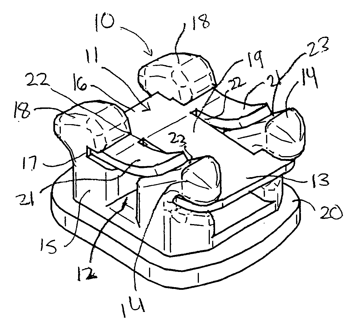
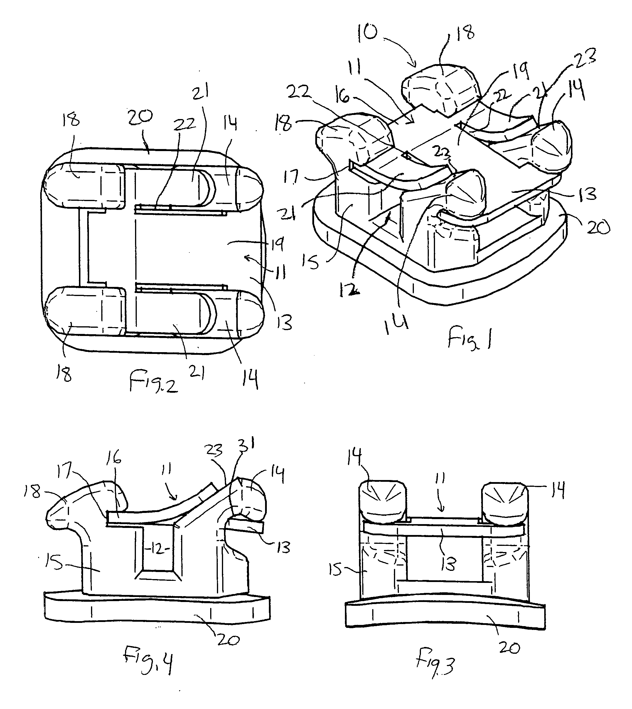
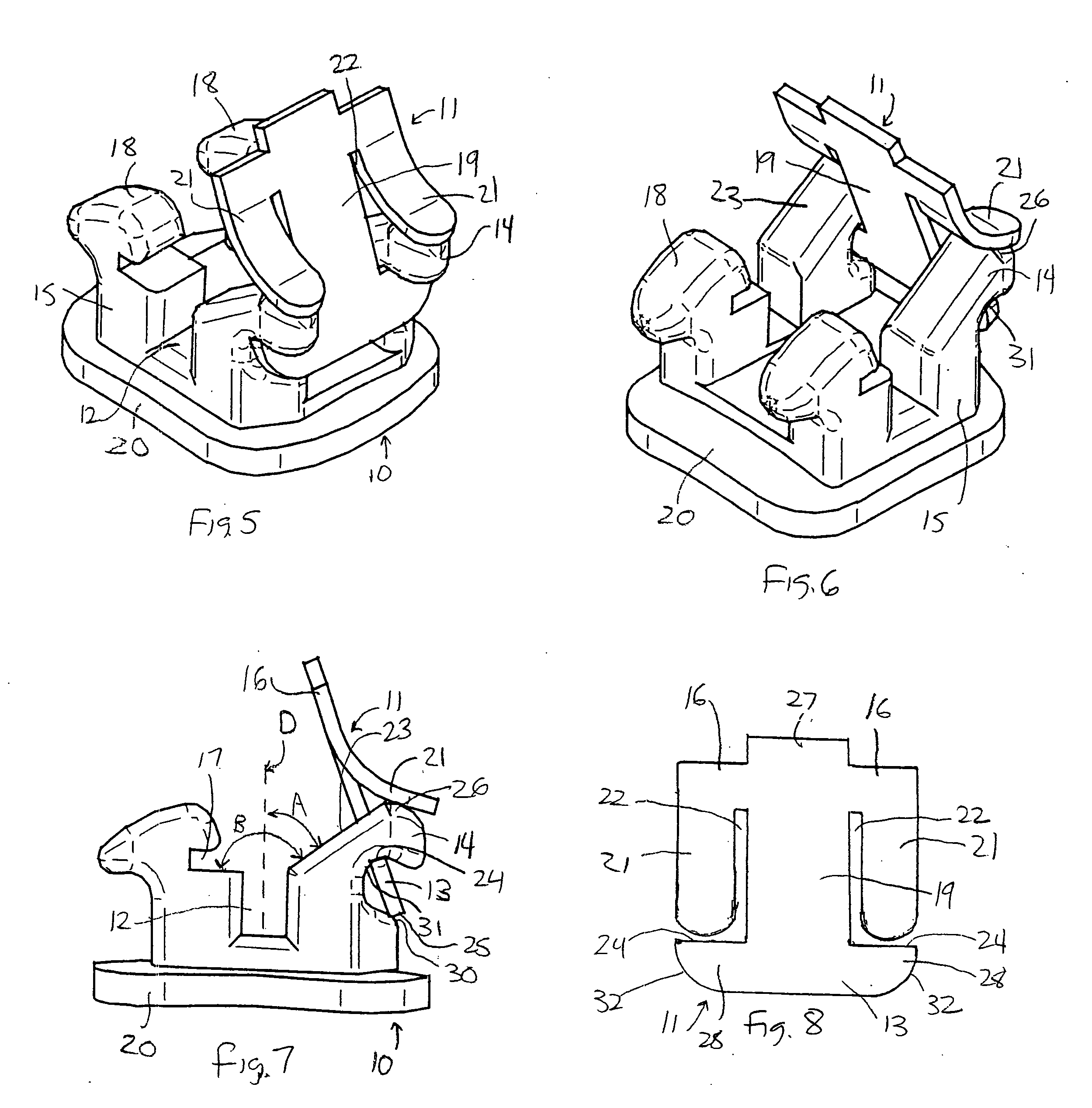
[0040] The invention is a self-ligating bracket system that relies on one or more arms or wings to lock the shutter or clip in place. Bracket systems are classified as either passive or active. A passive bracket system traps an archwire in the slot and creates an inflexible barrier when the archwire exerts force against it. An active or interactive bracket system is resilient, i.e. yields to some extent when the archwire moves against it, and exerts a counter force that tends to urge the archwire back into the slot. The examples discussed herein are of the passive type. The clip of the invention is resilient and bends when locking, exerting a resilient force. The resilient force is used to lock the clip, and it becomes a passive type of locking system.

[0041] With reference to FIGS. 1 to 8, a self-ligating bracket system of the invention includes a bracket 10 with a body 15 and base 20, and a clip 11 that is removably mounted thereon over the archwire slot 12. The clip 11 of the inv...


PUM


Abstract

An orthodontic bracket system includes a bracket having a base contoured to engage a tooth surface, a body extending from the base, at least one first tie wing connected to the body, and a pair of second tie wings connected to the body and spaced from the first tie wing in an occlusal-gingival direction when the bracket is mounted on a tooth. An archwire slot extends between the first and second tie wings in a mesial-distal direction, wherein the first tie wing has an outwardly inclined rear surface proximate the archwire slot. A clip for use with the bracket has a retaining portion configured to fit beneath the first tie wing on the side thereof opposite the archwire slot, a locking edge portion remote from the retaining portion that fits into a recess beneath the second tie wings, a mid-portion that spans the retaining portion and the locking edge portion and covers at least a portion of the archwire slot in a manner effective to retain an archwire therein, and at least one arm that extends from the locking edge portion towards the retaining portion and is spaced from the mid-portion. During closing, the arm rides down against the inclined rear surface of the first tie wing and a portion of the clip bends resiliently, exerting a force that locks the locking edge portion of the clip in the recess beneath the second tie wings. During opening, the arm rides up against the inclined rear surface of the first tie wing as the locking edge portion of the clip is removed from the recess beneath the second tie wings. The clip is then moved to an open position to permit placement and removal of the archwire and held in that position.

Description

[0001] This application claims priority of U.S. Provisional Application No. 60 / 721,392, filed Sep. 28, 2005.TECHNICAL FIELD [0002] The invention relates to brackets used in orthodontic treatment, more specifically to an orthodontic bracket having a clip or latch for releasably retaining an archwire in an archwire slot of the bracket. BACKGROUND OF THE INVENTION [0003] During one type of common orthodontic treatment, a series of small brackets are fixed to a patient's anterior, cuspid and bicuspid teeth, and an archwire is inserted into a slot of each bracket. The archwire forms a track to guide movement of the teeth to orthodontically correct locations. End sections of the archwires are typically captured in tiny appliances known as buccal tubes that are fixed to the patient's molar teeth. Many types of orthodontic brackets have archwire slots that are open on one side for insertion of the archwire, and confined on remaining sides by the bracket tie wings or other structure. Bracket...

Claims


Application Information

Patent Timeline
IPC IPC(8): A61C3/00
CPCA61C7/285A61C7/28
Inventor SOMMER, JAY S.
Owner AMERICAN ORTHODONTICS
Why Eureka
Try Eureka