Pole Retention Configuration For Electric Machine Rotors

a technology of electric machines and rotors, which is applied in the direction of dynamo-electric machines, magnetic circuit rotating parts, magnetic circuit shapes/forms/construction, etc., can solve the problems of rare earth magnets, brittleness, and difficult operation of permanent magnet motors in severe-duty applications, and achieves easy manufacturing tolerances.

Active Publication Date: 2010-09-16
DRS NAVAL POWER SYST INC
View PDF11 Cites 34 Cited by
  • Summary
  • Abstract
  • Description
  • Claims
  • Application Information

AI Technical Summary

Benefits of technology

[0013]In accordance with principles of the invention, a retention system can be provided in which manufa

Problems solved by technology

The use of permanent magnet motors in severe-duty applications is often hampered by difficulties in protecting the rotor magnets and retaining them on the rotor rim during high centrifugal loading.
Under severe cyclic duty, rare earth magnets, e.g., NdFeB magnets, which can be very brittle, can experience heavy shock and vibration loads as well as high centrifugal forces.
In some cases, the rotor experiences frequent and abrupt torque reversals that demand that the retention system also minimize assembly tolerances.
Excessive magnet/retention system assembly clearances could permit movement of the magnets within the retaining configuration and cause damage to the magnets themselves.
To compound matters, the magnets are inhere

Method used


Image

  • Pole Retention Configuration For Electric Machine Rotors
  • Pole Retention Configuration For Electric Machine Rotors
  • Pole Retention Configuration For Electric Machine Rotors

Examples


Embodiment Construction

[0030]Reference will now be made to an implementation consistent with the present invention as illustrated in the accompanying drawings. Wherever possible, the same reference numbers will be used throughout the drawings and the following description to refer to the same or like parts.

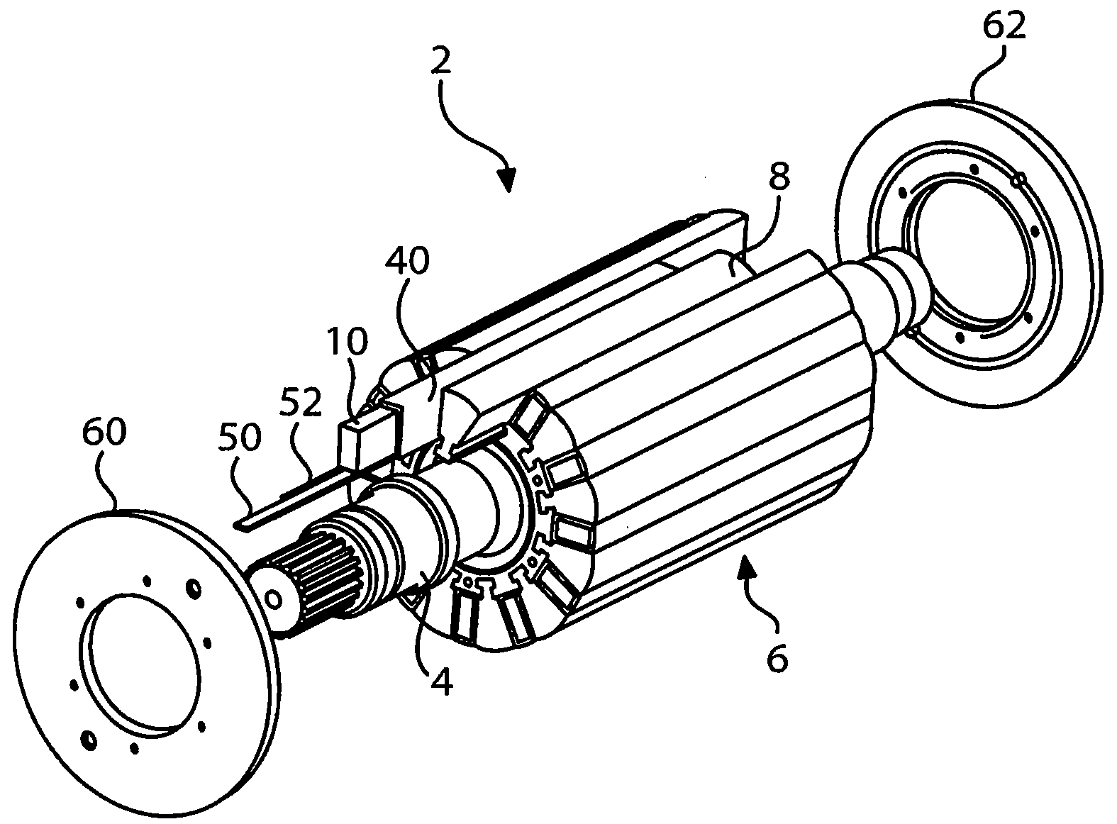
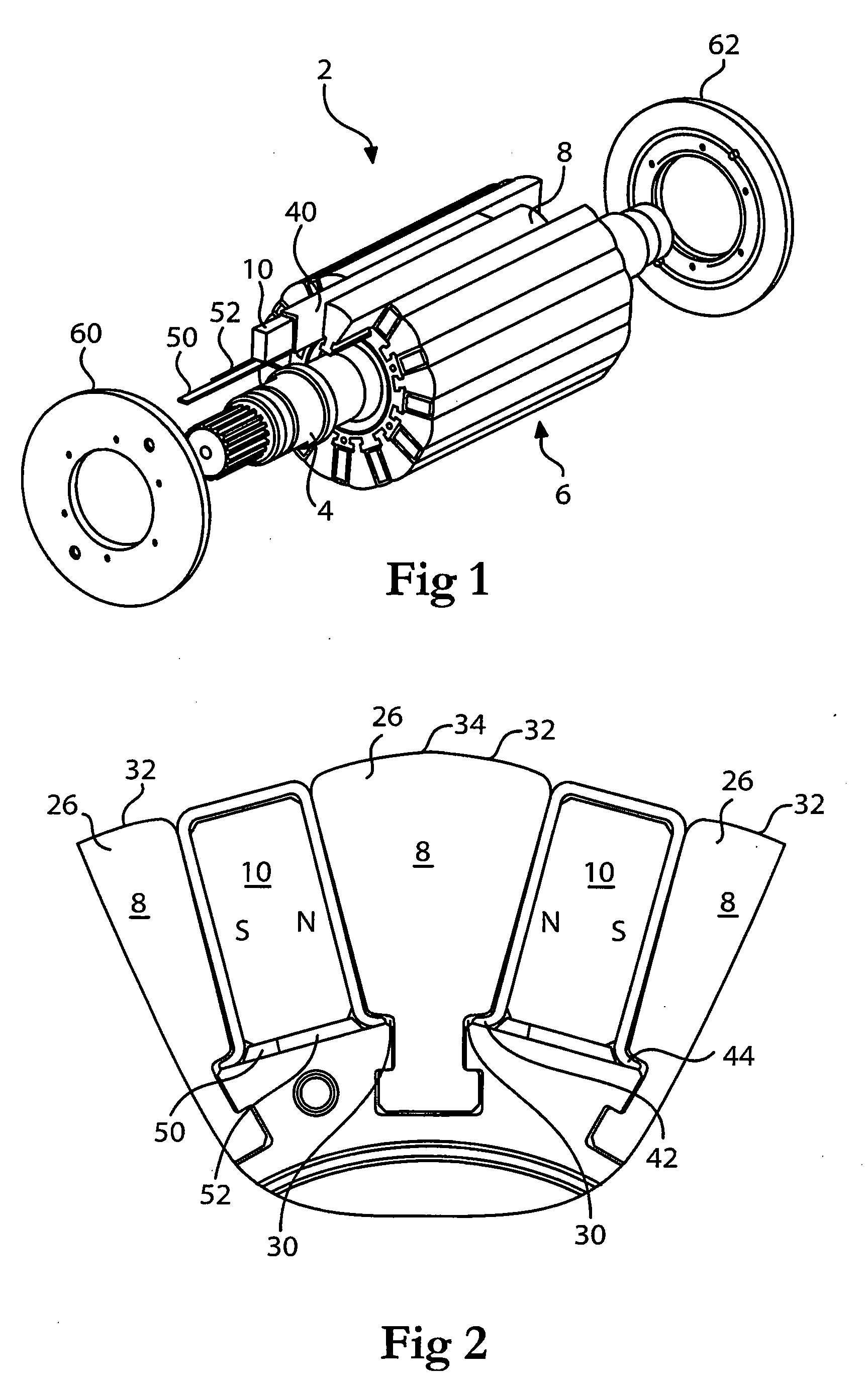
[0031]In FIG. 1, there is illustrated a rotor assembly 2, useful in permanent magnet electric machines. Generally, the rotor assembly 2 includes a suitably configured shaft 4 having a rotor hub or rotor tire 6 secured thereto or a part thereof that extends axially along and circumferentially about the shaft 4. As described in greater detail below, the hub or tire 6 is suitably configured to accept therein and thereon pole pieces 8 and permanent magnets 10.

[0032]The rotor hub 6 preferably is constructed of one or more nonmagnetic materials.

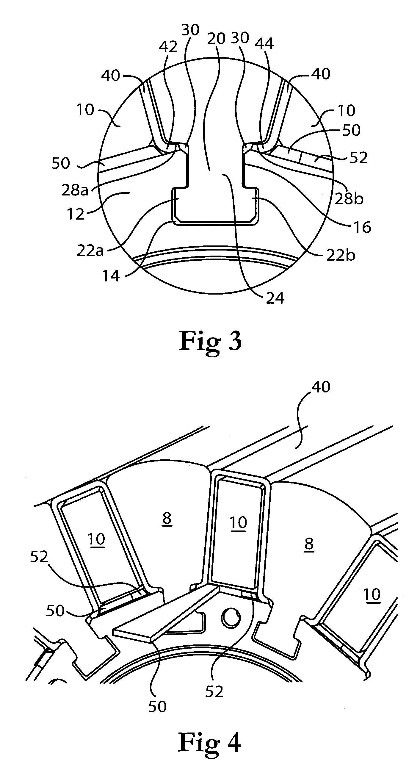
[0033]With reference also to FIGS. 2-4, where an end portion of the rotor hub 6 is illustrated in various ways, the hub 6 includes axially-extending channels 12 formed...


PUM


Abstract

A retention system in which rotor pole pieces are retained within complementarily shaped channels in a rotor hub, permanent magnets are secured between the pole pieces and within clamp members, and wedge-shaped pieces are used to apply positive locking forces along the axial length of each clamp member and of adjacent pole pieces. A curable resin preferably in disposed within gaps between the permanent magnets and the clamp members.

Description

[0001]This invention generally relates to electric machines such as permanent magnet heavy-duty electric machines, including generators and motors. More particularly, the invention relates to configurations for securing rotor pole pieces and permanent magnets relative to the rotors in relatively heavy duty rated machines.BACKGROUND OF THE INVENTION[0002]The use of permanent magnet motors in severe-duty applications is often hampered by difficulties in protecting the rotor magnets and retaining them on the rotor rim during high centrifugal loading. Under severe cyclic duty, rare earth magnets, e.g., NdFeB magnets, which can be very brittle, can experience heavy shock and vibration loads as well as high centrifugal forces. In some cases, the rotor experiences frequent and abrupt torque reversals that demand that the retention system also minimize assembly tolerances. Excessive magnet / retention system assembly clearances could permit movement of the magnets within the retaining configu...

Claims


Application Information

Patent Timeline
IPC IPC(8): H02K1/28
CPCH02K1/2773
Inventor IFRIM, COSTINPOTHIER, MICHAELSMITH, JAMES S.O'LEARY, ART
Owner DRS NAVAL POWER SYST INC
Why Eureka
Try Eureka