Method and device for deciding support portion position in a backup device

a technology for determining the position of the support portion and the backup device, which is applied in the direction of instruments, analogue processes for specific applications, electric/magnetic computing, etc., can solve the problems of high precision, serious problems, and the mounting position of the component is made off the target, so as to reduce the cost involved and achieve high precision the effect of mounting

Active Publication Date: 2007-03-29
FUJI MASCH MFG CO LTD
View PDF11 Cites 14 Cited by
  • Summary
  • Abstract
  • Description
  • Claims
  • Application Information

AI Technical Summary

Benefits of technology

[0017] With this construction, since setting is made as to whether each support place of the backup device is to serve as the flexure preventing support place for preventing the flexure of the board or as the particular component support place for supporting the particular component which requires high

Problems solved by technology

On the other hand, with the speeding-up of the mounting tact-time, there arises a problem that the mounting position for a component is made off the target by the shock at the time of the component mounting operation.
This problem becomes serious in the case of components (e.g., QFP, SOP, BGA, CSP etc.) which are required to be mounted with particularly

Method used


Image

  • Method and device for deciding support portion position in a backup device
  • Method and device for deciding support portion position in a backup device
  • Method and device for deciding support portion position in a backup device

Examples


Embodiment Construction

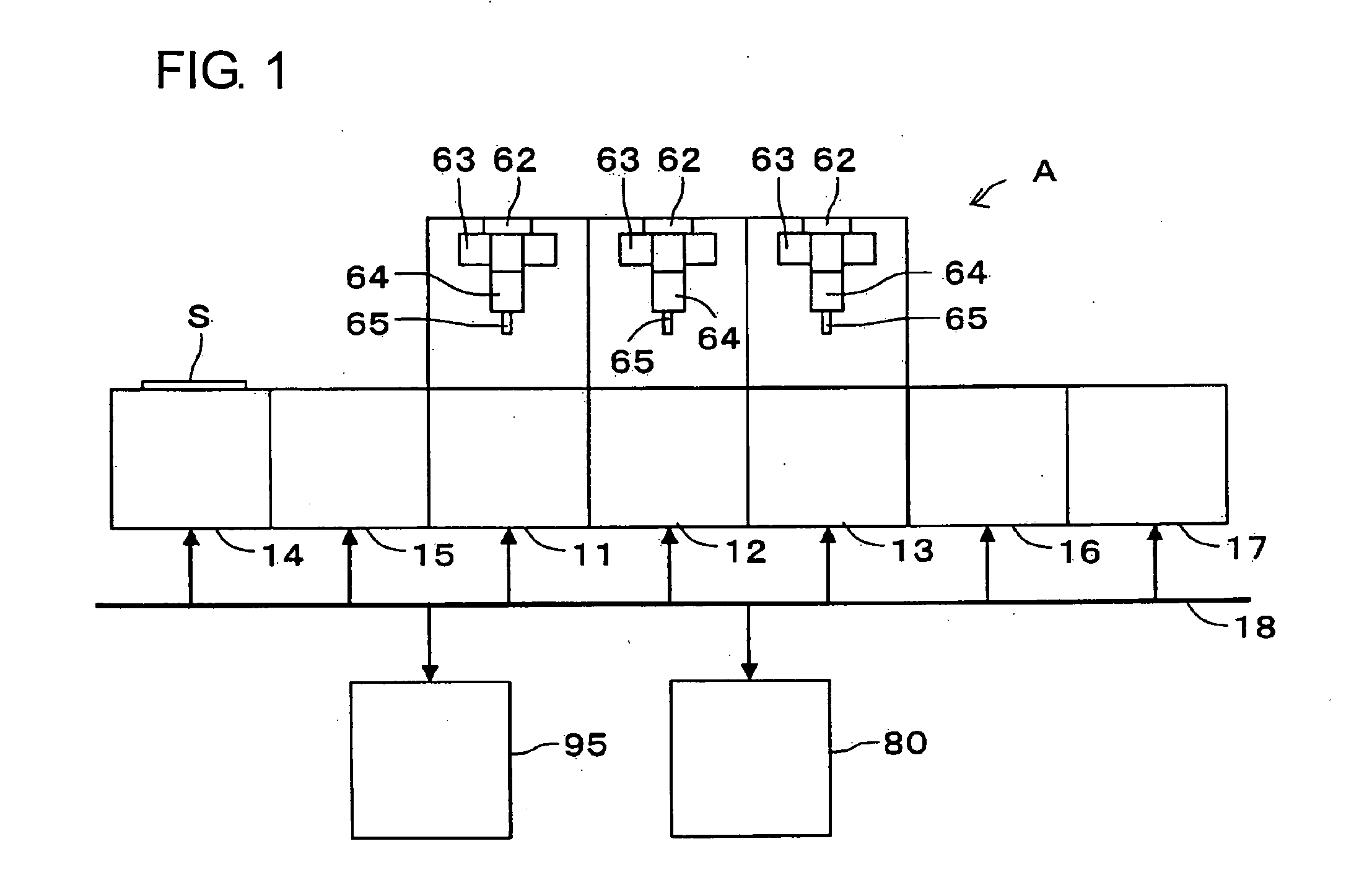
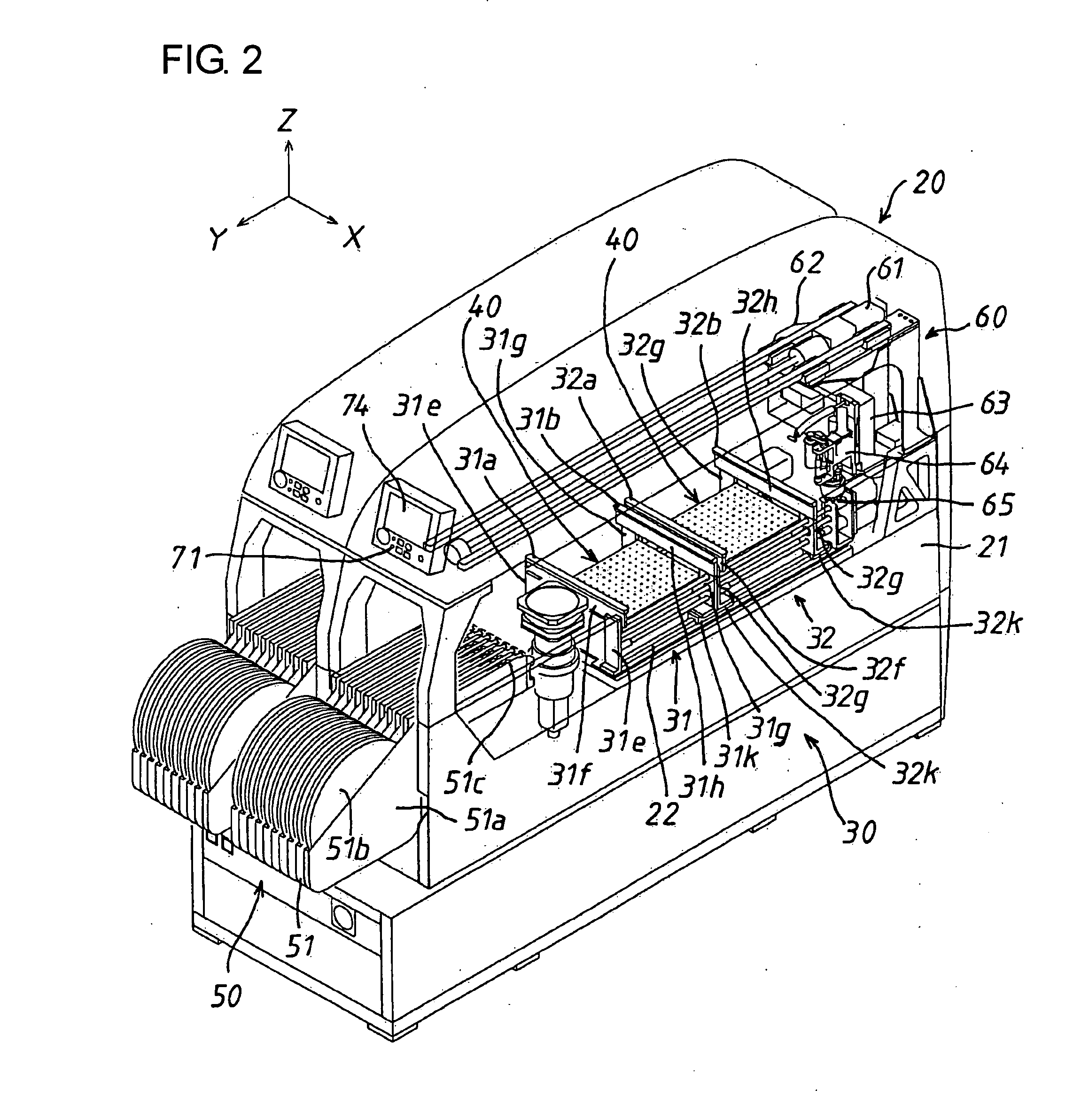
[0038] Hereafter, description will be made regarding an electronic component mounting line in one embodiment which has applied thereto a support place position determination method and a support place position determination device according to the present invention. FIG. 1 shows a schematic construction of the electronic component mounting line A, FIG. 2 shows the entire constructions of electronic component mounting apparatuses, and FIG. 3 mainly shows a sectional view of a backup device. It is to be noted that FIG. 2 shows two electronic component mounting apparatuses mounted on a single base.

[0039] The electronic component mounting line A takes the construction that first to third electronic component mounting apparatuses 11 to 13, that is, three electronic component mounting apparatuses 20 are arranged in series. A solder printer 14 for applying cream solder to predetermined places on each board S and an adhesive application machine 15 for applying component adhering adhesive t...


PUM


Abstract

A host computer 80 for wholly controlling an electronic component mounting line displays a surface side image and a reverse side image which respectively show a surface side and a reverse side of a board having components mounted thereon, with the images being superposed; displays components mounted on the surface side of the board and components mounted on the reverse side in visually different modes; and designates and determines the positions of support places of a backup device on the displayed superposed image (step 108).

Description

TECHNOLOGICAL FIELD: [0001] The present invention relates to a support place position determination method and a support place position determination device for determining the positions of support places of a backup device which supports a board. BACKGROUND ART [0002] Heretofore, there has been well known a backup device which constitutes an electronic component mounting apparatus for mounting components on a board and which supports the board. As the backup device, there is one in which plural backup pins for supporting a board at the reverse side in mounting electronic components are planted to be removably insertable into plural pin holes opening on a backup plate. In the backup device, the backup pins have practically been planted at positions where the backup pins are to be planted in dependence on the kinds of boards to be produced. That is, the positions for enabling the backup pins to support the board are distinguished in dependence on the kind of each board, and the plant...

Claims


Application Information

Patent Timeline
IPC IPC(8): G06F19/00H05K13/04H05K13/08
CPCH05K13/08H05K13/0061
Inventor OOHASHI, TERUYUKIKURASHINA, TAKASHI
Owner FUJI MASCH MFG CO LTD
Why Eureka
Try Eureka