Supporting stand

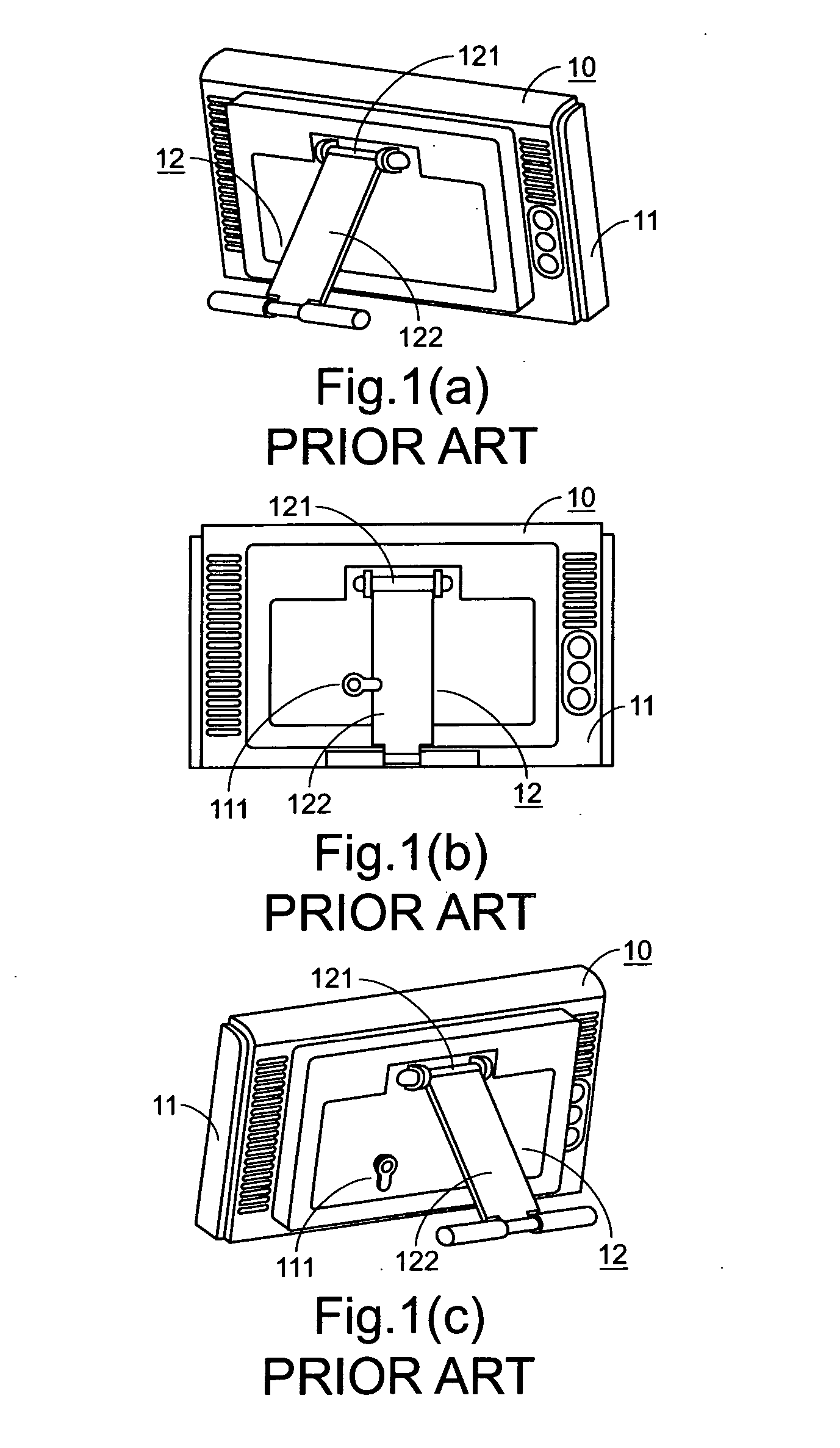
a support and stand technology, applied in the field of supporting stands, can solve the problems of loss of securing function, increased production cost and processing time, and easy damage of the hinge coupler 121/b>,

Inactive Publication Date: 2007-04-05
AVERMEDIA TECH
View PDF12 Cites 65 Cited by
  • Summary
  • Abstract
  • Description
  • Claims
  • Application Information

AI Technical Summary

Benefits of technology

[0013] In an embodiment, the back plate, the prop plate and the platform are substantially maintained as a triangular configuration when the center of gravity of the object reaches static force balance, such that the weight of the object is evenly distributed to the bottom of the back plate and the prop plate to have the object stand on the platform in the upright manner.

Problems solved by technology

In addition, since the prop plate 122 of the foot stand 12 is frequently adjusted to maintain desired angle of the display panel 11, the hinge coupler 121 is readily damaged and subject to fatigue.
For example, since the fixing member 111 is protruded from the back side of the display panel 11, the fixing member 111 is readily damaged due to an improper force exerted thereon and thus the securing function thereof is lost at that moment.
Therefore, additional production cost and processing time are required.

Method used


Image

  • Supporting stand
  • Supporting stand
  • Supporting stand

Examples


first embodiment

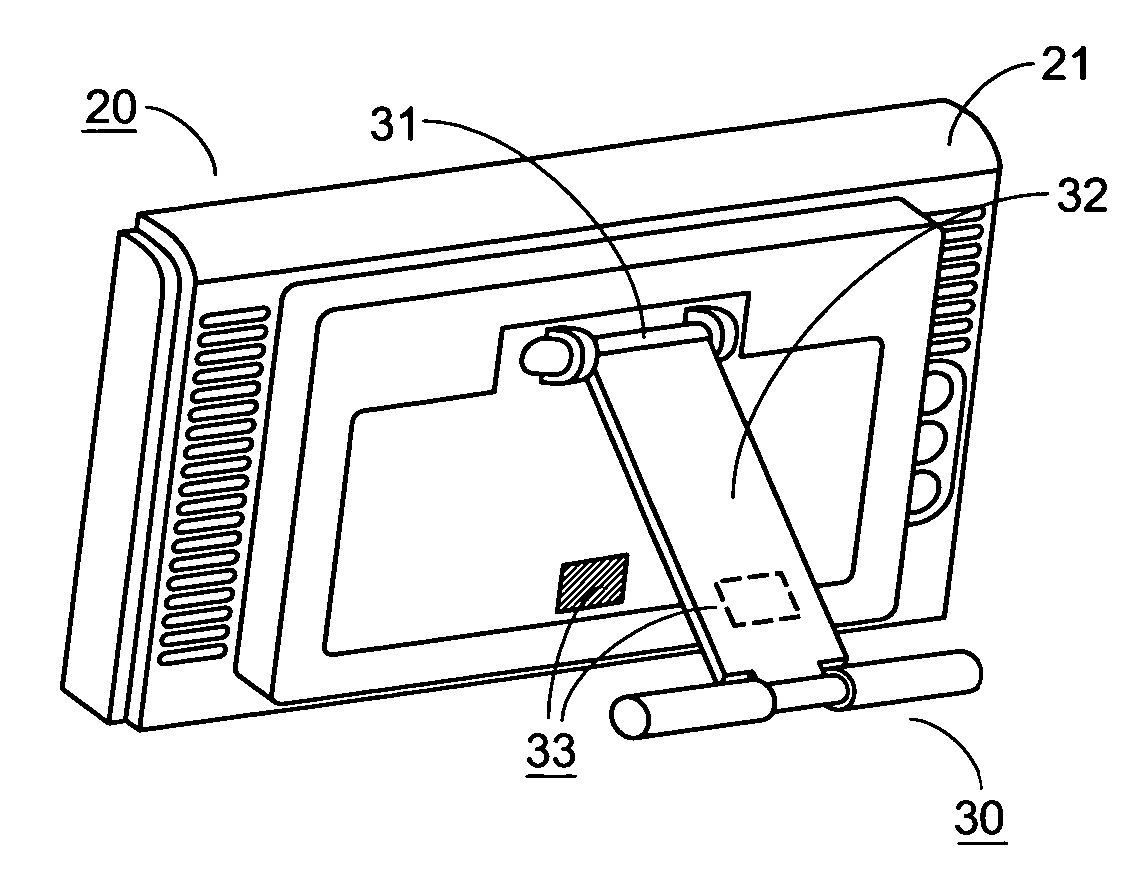
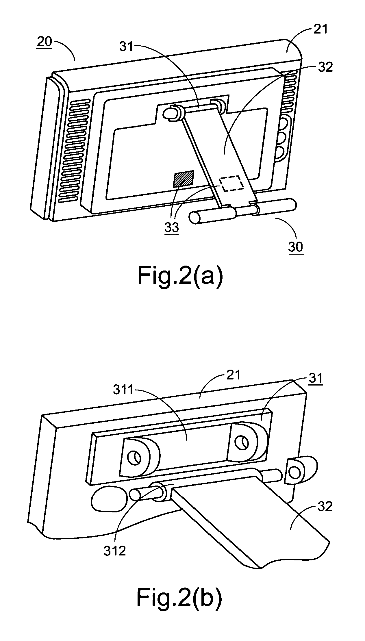
[0036] In the first embodiment, the first magnetic element 331 and the second magnetic element 332 are arranged on the prop plate 32 and the back plate 21, respectively. It is noted that, however, those skilled in the art will readily observe that numerous modifications and alterations may be made while retaining the teachings of the invention. For example, corresponding portions of the prop plate 32 and the back plate 21 may be made of the magnetic substances, so that the prop plate 32 and the back plate 21 are magnetically coupled to each other due to magnetic attraction. In this instance, the supporting stand 30 is collapsed to the possible minimum compact size.

[0037] After the prop plate 32 of the supporting stand 30 is collapsed onto the back plate 21, as is shown in FIG. 2(d), the prop plate 32 is securely fixed onto the back plate 21. In addition to maintaining smoothness of the back plate 21, the second magnetic element 332 has satisfactory concealment. Therefore, the proble...

second embodiment

[0038] Referring to FIG. 2(e), the schematic diagram of the coupling member 33 according to the present invention is illustrated. In this embodiment, the second magnetic element 332 is buried within the back plate 21 and at the location corresponding to the first magnetic element 331. In such manner, the surface of the back plate 21 is kept smooth and the supporting stand 30 is also collapsed to the possible minimum compact size. The other components included therein are similar to those described in the first preferred embodiment, and are not redundantly described herein. In this embodiment, since the second magnetic element 332 is buried within the back plate 21, the back plate 21 is very clean in appearance.

[0039] Please refer to FIG. 2(f), which is a schematic diagram illustrating that the prop plate of the supporting stand is collapsed onto the back plate according to the second preferred embodiment of the present invention. Although the second magnetic element 332 is buried wi...


PUM


Abstract

A supporting stand for supporting an object includes a hinge coupler, a prop plate and a coupling member. The hinge coupler is fixed onto a back plate of the object. The prop plate is coupled to the hinge coupler and permissible for multi-angle rotation. When the prop plate is rotated to a desired position where the center of gravity of the object reaches static force balance, the object will stably stand on a platform in an upright manner. The coupling member includes a first magnetic element and a second magnetic element, which are respectively arranged on the prop plate and the back plate. The first magnetic element and the second magnetic element are magnetically coupled to each other when the prop plate is collapsed onto the back plate. In response to a specified operation, the first magnetic element is detached from the second magnetic element such that the prop plate is rotated to the desired position to have the object stand on the platform in the upright manner.

Description

FIELD OF THE INVENTION [0001] The present invention relates to a supporting stand, and more particularly to a supporting stand for supporting an object such as a small-size liquid crystal display (LCD) or a photo frame. BACKGROUND OF THE INVENTION [0002] With increasing development of high technology industries, a variety of new high-tech products are brought forth and the old ones are weeded out soon. In modern society, handheld electronic devices such as mobile phones, notebook computers, personal digital assistants (PDAs), small-sized liquid crystal displays (LCDs), handheld game devices, etc. become essential electronic devices because they are feasible to be used in many instances. For example, the handheld electronic devices are often used in our daily lives or workplaces, or otherwise employed for teaching or amusement purposes. On account of their portability, the users can use such handheld electronic devices wherever and whenever they are. In addition to convenience and am...

Claims


Application Information

Patent Timeline
Patent Type & Authority Applications(United States)
IPC IPC(8): A47G1/24
CPCF16M13/00F16M11/10F16M13/005F16M2200/02F16M2200/08A47G1/06A47G1/142G09F1/10
Inventor CHEN, CHAO-JUNG
Owner AVERMEDIA TECH
Why Eureka
Try Eureka