Calibration method for a printer

a printer and calibration method technology, applied in printing, other printing apparatus, etc., can solve the problems of incomplete or inaccurate conclusions on the characteristic of the mechanism, and achieve the effect of improving the scanning effect of the human eye and improving the stability of the sensor reading

Active Publication Date: 2007-04-05
HEWLETT PACKARD DEV CO LP
View PDF3 Cites 9 Cited by
  • Summary
  • Abstract
  • Description
  • Claims
  • Application Information

AI Technical Summary

Benefits of technology

[0027] In an embodiment, the base pattern is printed using a first nozzle and the overlay pattern is printed using a second nozzle, the first and the second nozzle being separated by an inter nozzle distance along the direction of media advance, the inter nozzle distance corresponding to the predetermined distance. In this embodiment, if the base pattern is a line and the overlay pattern is also a line, and if the predetermined distance is exactly equal to the inter nozzle distance, the lines will exactly overlap. The same would apply if the base pattern was a dot and if the overlay pattern was also a dot. It should be understood that the predetermined distance corresponds to both an input and an output of the mechanism. If the system is perfect, the output will exactly correspond to the input, and to the inter nozzle distance. In a real system, there is a possibility that the output will not correspond to the input, and there is a possibility that the inter nozzle distance will not correspond to any of the input or output. In such a case, the base pattern and the overlay pattern will not exactly superpose, which leads to forming the interference pattern. In a further embodiment, the overlay pattern is printed using a group of nozzles, the group of nozzles extending along the direction of media advance, the second nozzle being located in the central zone of the group of nozzles. In this particular case, the base pattern may be used as a reference, and the overlay pattern for screening. More specifically, the base pattern may comprise a line and the overlay pattern a number of parallel and shifted steps forming a stair like structure, the stair like structure having a length along a direction perpendicular to the direction of medium advance equal to the length of the line of the base pattern, in such a manner that a given step of the stair may be coincident or overlap the line of the base pattern depending on the system variables, the printer variables being the swath height and the characteristic of the mechanism, in such a way that in a perfect printer, the step printed by the second nozzle located in the central zone would overlap the line printed by the first nozzle. In an embodiment, the group of nozzles comprises consecutive nozzles. In an embodiment, the resulting interference pattern is optically evaluated by an optical sensor. It should be noted that the sensor typically has a known or estimated field of view, which may be circular, elliptical or the like, and for which a characteristic diameter or average diameter may be defined. In an embodiment, each step of the stair forming the overlay pattern as defined above has a length corresponding to at least one characteristic diameter of the field of view. In another embodiment, each step of the stair forming the overlay pattern as defined above has a length corresponding to at least 5 times the characteristic diameter of the field of view in order to improve the stability of the sensor reading.
[0028] In an embodiment, the base pattern is printed in two steps, the medium being advanced by the mechanism between the two steps in a direction opposite to the direction of advancing the medium of the predetermined distance according to step e-. This particular embodiment allows applying the invention to the calibration of so-called “one-pass” print mode. A particular print mode is typically related to a number of passes of a printhead on a given place of the medium for obtaining the picture. A two-pass print mode implies that the printhead will pass twice at each given point of the medium to produce the final result. This clearly has a relationship to the speed of the process, in so far as a one-pass print mode would be more or less twice as fast as a two-pass print mode. The quality of a picture made using a two-pass print mode will however likely be higher that the quality of the same picture using a one-pass print mode. The number of passes also relates to the advance of the medium. For example, in a two-pass print mode, the medium is typically advanced in steps of half a swath height. In a one pass print mode, the medium is normally advanced of a full swath height. When calibrating the printer for a one pass print mode, the advance of the medium should be of en entire swath height. Indeed, in an embodiment, the medium is advanced by the mechanism between the two base pattern steps of a distance corresponding to the entire swath height. In order to produce the overlay pattern, in a further embodiment, the predetermined distance corresponds to a half of the swath height. In a particular embodiment, the base pattern comprises a line perpendicular to the direction of media advance. In a further embodiment, the overlay pattern comprises an approximation of a line at an angle to the said line of the base pattern. Typically, such an approximation is formed of steps forming stairs centered on the theoretical desired line. In another embodiment, the line approximation comprises at least one transition zone, the transition zone being obtained using a first and a second nozzle separated by a space along the direction of media advance, the first nozzle firing with a generally decreasing frequency and the second nozzle firing with a generally increasing frequency to form the transition zone. In a specific embodiment, the interference pattern is visually scanned by human eye. In a further embodiment, a reference grid is provided to improve scanning by the human eye.

Problems solved by technology

This means that an analysis which does not take the swath height into account will lead to conclusions on the characteristic of the mechanism which are not exact or not complete.

Method used


Image

  • Calibration method for a printer
  • Calibration method for a printer
  • Calibration method for a printer

Examples


first embodiment

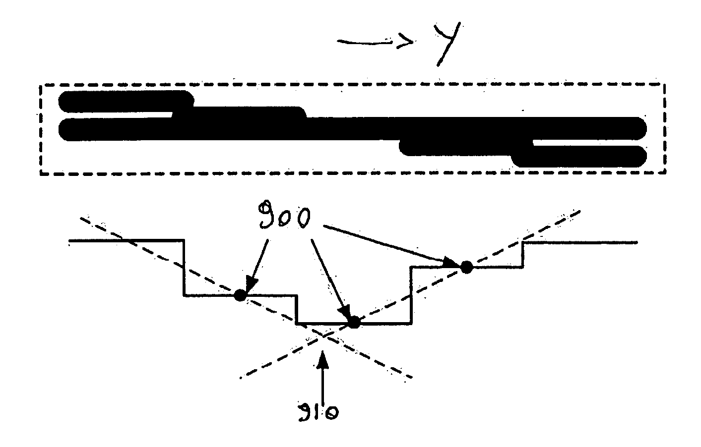
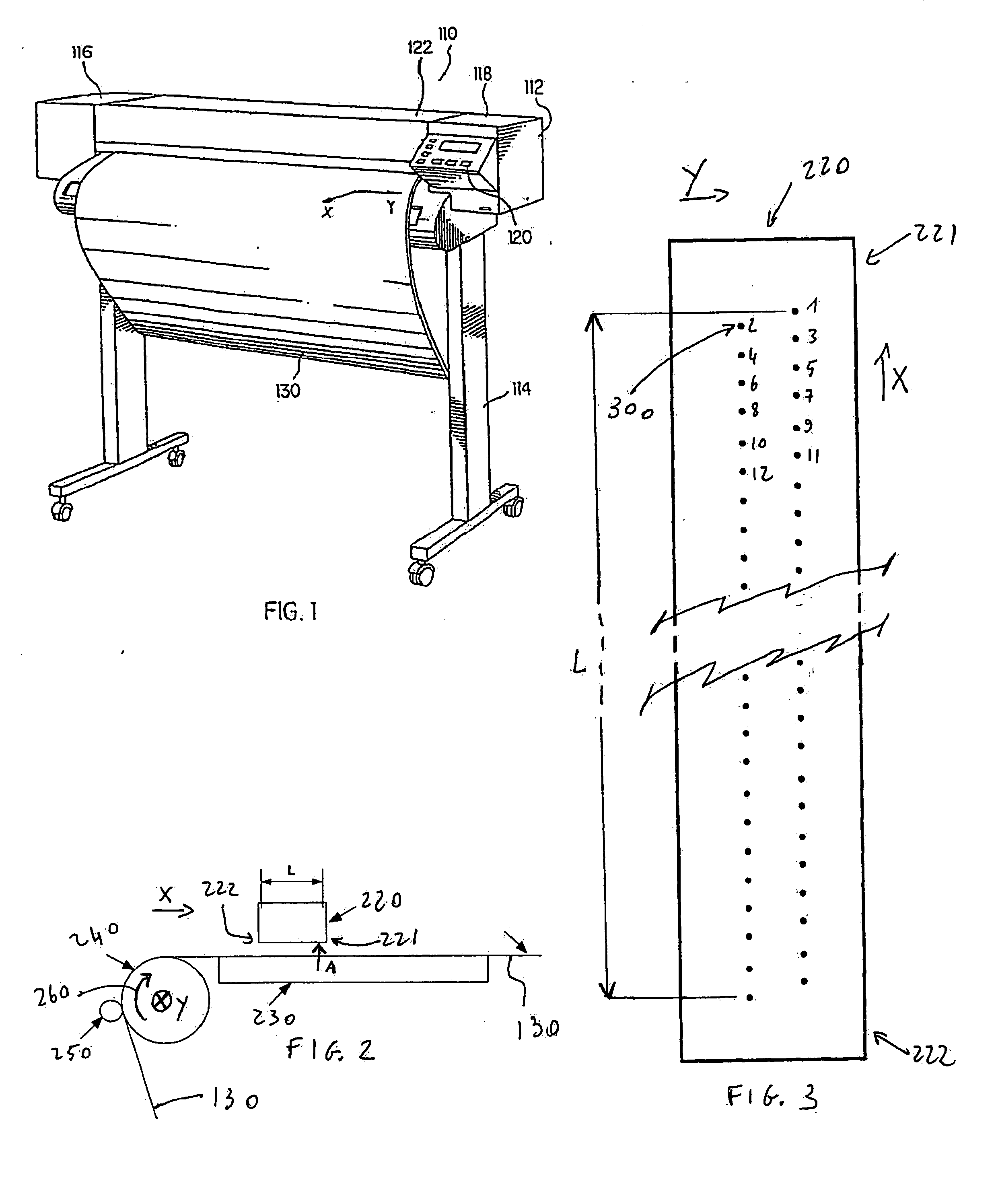
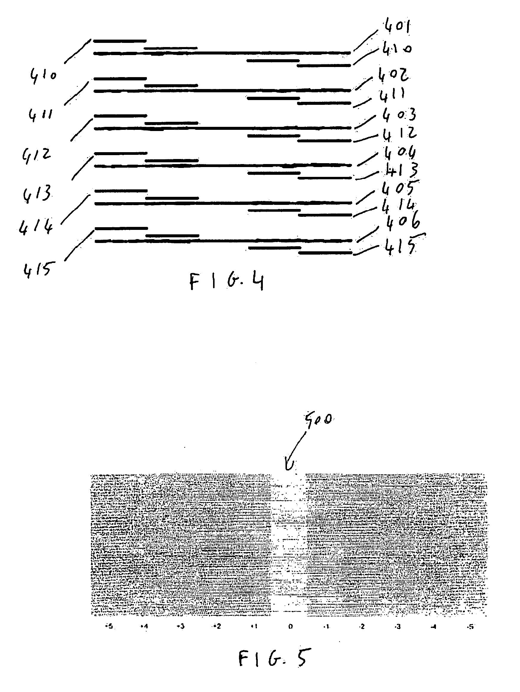
[0046] One of the mechanism characteristic or of the swath height being known or estimated, an interference pattern as represented on FIG. 4 is printed as follows according to the invention. In a first pass of the printhead, the printhead prints lines 401 to 406. These lines are printed using 6 nozzles separated by 10 nozzles. In the example, the printhead has two columns of nozzles, the nozzles being staggered. We will assume that the nozzles of a first column are described with odd numbers starting from the end 221 of the printhead 220 further away from the drive roller 240 (nozzles 1, 3, 5, 7 etc . . . ) and that the nozzles of a second column are described with even numbers starting from the same end 221 (2, 4, 6, 8, etc . . . ) such that along the X axis the nozzles follow each other in the order 1, 2, 3, 4, 5 etc . . . , the nozzle number 1 being located on the end 221 of the printhead further away from the drive roller. Line 401 is printed by nozzle 6, line 402 is printed by ...

third embodiment

[0052] In a third embodiment, the intrinsic precision is improved and the improved result is obtained without extrapolation.

[0053] In the third embodiment, the overlay pattern is not made of steps but made of the approximation of a line at an angle to the corresponding line of the base pattern, the line of the base pattern being along the Y direction, i.e. perpendicular to the direction of media advance. In the third embodiment, the approximation of the line at an angle being built with steps similar to the steps of FIG. 4, whereby one of every two steps is formed by alternating segments 1101 and blanks 1102 whereby the concentration of blank spaces increases progressively relative to the concentration of segments, or whereby the size of the blanks progressively increases relative to the size of the segments in the positive sense of the Y direction, in such a manner that the step fades away in the Y direction indicated in FIG. 11. The other steps are built in the opposite manner, by...

fourth embodiment

[0054] It should however be noted that the optical intensity of the overlay pattern was found to be higher in the centre 1300 of the transition fading zone than in the edges 1310 and 1320 due to the fact that the drops forming the print overlap when contiguous, such as towards the edges, and do not overlap or overlap to a lesser extend in the central zone 1300, so that the local concentration of printed area is higher in the central zone than at the edges. This non homogeneity of the optical intensity may have a negative influence on the reading by the optical sensor, and was corrected in a fourth embodiment where an additional overlay pattern was inserted between the previously described overlay pattern, but in opposition of phase so as to re-equilibrate the optical density, as illustrated in FIG. 12. It should be noted that both in FIGS. 11 and 12 only two steps of the overlay pattern equivalent to the overlay of FIG. 4 are represented. The base pattern itself remains unchanged. A...


PUM


Abstract

The invention relates to a calibration method for a printer having a mechanism for advancing a medium in a direction of media advance comprising the following steps: a- providing a printhead, the printhead having a swath height in the direction of media advance; b- providing an estimate of either the swath height or the characteristic of the mechanism; c- printing a base pattern on a medium using the printhead; d- printing an overlay pattern on the medium using the printhead to form an interference pattern; e- advance the medium of a predetermined distance using the mechanism at a time between the printing of the base pattern and the printing of the overlay pattern; f- analyze an optical evaluation of the interference pattern; g- evaluate as either: i- the swath height if the characteristic of the mechanism is known or estimated; or ii- the characteristic of the mechanism if the swath height is known or estimated.

Description

FIELD OF THE INVENTION [0001] The present invention relates to the field of calibration of printers. BACKGROUND OF THE INVENTION [0002] Printers are electromechanical assemblies which are used to produce pictures, the quality of the pictures produced being highly dependent on the accuracy of the calibration of the printer. The calibration process for a printer is typically the result of a variety of methods or measurements, such calibration methods occurring during or directly following the manufacturing process, but sometimes also during the actual life of the printer to make adjustments. PRIOR ART [0003] A specific calibration method has for example been disclosed in EP1211084, where an interference pattern is printed, the interference pattern being scanned by a sensor, the results of the scan being analyzed to lead to the linefeed calibration of the printer. [0004] Due to the increasing complexity of the electromechanical arrangement forming a printer it is difficult to evaluate ...

Claims


Application Information

Patent Timeline
Patent Type & Authority Applications(United States)
IPC IPC(8): B41J29/393
CPCB41J29/393
Inventor PLANTE, JEAN FREDERICANDREA, ALEXRUIZ, PASCALCAMPDERROS, JOANBARAMBIO, ANGEL MARTINEZCAMPILLO, ALEJANDROCASALDALIGA, MARCOS
Owner HEWLETT PACKARD DEV CO LP
Why Eureka
Try Eureka