Irregular, tessellated building units

a technology of tessellated building units and random patterns, applied in the direction of single unit paving, outline designs, paths, etc., can solve the problems of labor intensive, high cost, random patterns of manufactured units not having the degree of natural irregularity, etc., to enhance natural beauty, improve structural connection, and custom appearance

Inactive Publication Date: 2007-04-05
KEYSTONE RETAINING WALL SYST
View PDF36 Cites 81 Cited by
  • Summary
  • Abstract
  • Description
  • Claims
  • Application Information

AI Technical Summary

Benefits of technology

[0012] Further applications of the invention are vertical and three dimensional structures such as walls, columns, containers and other structures. Each unit has a tessellated front face comprising one or more primary elements as described above, sides extending substantially perpendicularly from the front face, and a rear face. Preferably, connectors such as lugs or notches are provided to improve the structural connection between units. A structure, such as retaining wall, constructed of such units having different sizes and shapes will have a natural and custom appearance.
[0013] A preferred, optional feature of the invention is a building unit h

Problems solved by technology

It is labor intensive, and accordingly expensive.
However, random patterns of manufactured units do not have the

Method used


Image

  • Irregular, tessellated building units
  • Irregular, tessellated building units
  • Irregular, tessellated building units

Examples


first embodiment

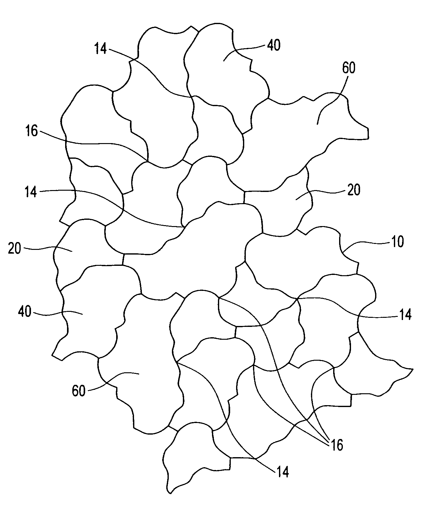
[0081]FIG. 1 shows a surface covering 10 constructed in accordance with the present invention. Surface covering 10 comprises an arrangement of building units without substantial gaps or overlapping. Building units may be molded or otherwise made of concrete, stone, ceramics, plastic, natural or synthetic rubber, glass or other suitable material, or combinations thereof. In FIG. 1, surface covering 10 is comprised of three different sized units 20, 40 and 60. The units have what appear to be irregular configurations. Further, the surface covering 10 has the appearance of a natural, custom surface, i.e., there is no readily apparent repeating pattern.

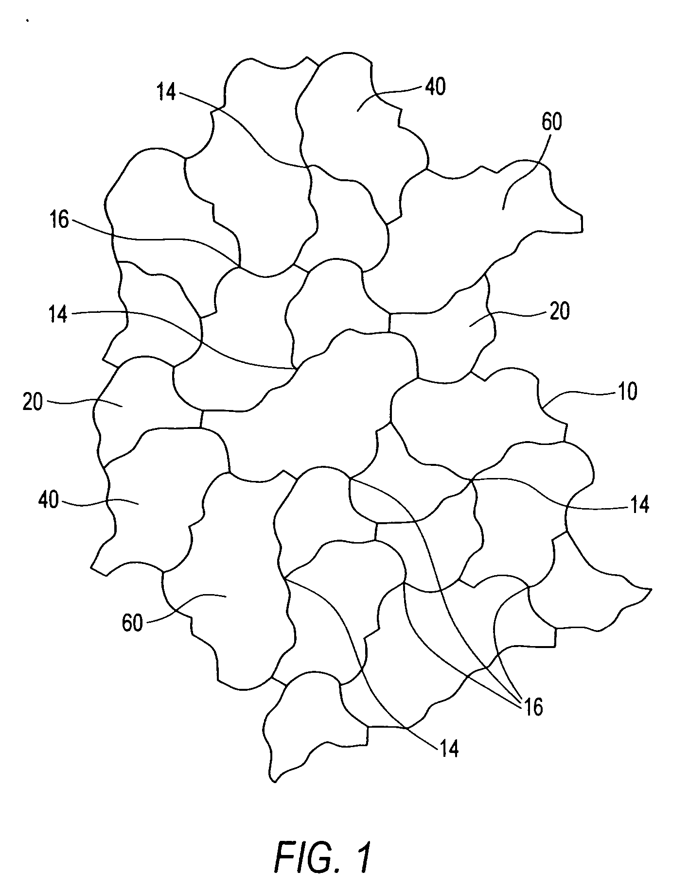
[0082] An enlarged view of unit 20 is shown in FIG. 2. The unit comprises a single primary element 20 of a rotational tessellation as will be described in greater detail below. Primary element 20 has a first side 22 extending between points A and B. Second side 24 extends between points A and E. A transverse side 26 extends between points...

second embodiment

[0092]FIGS. 11-16 illustrate building units and an exemplary surface covering of a rotational tessellation element of the invention. FIG. 11 shows a primary element 120 comprised of six sides, namely, first side 122 extending between points A and B, second side 124 extending between points A and F, third side 128 extending between points B and C, fourth side 130 extending between points C and D, fifth side 131 extending between sides D and E and sixth side 133 extending between points E and F. Together, sides 3 to 6 form transverse side 126. Element 120 has three vertices, namely, first vertex 134, second vertex 136, and third vertex 137. First 122 and second 124 sides are irregular, rotational images of one another, radiate from first vertex 134, and are rotationally spaced by an angle θ of 60 degrees. The third 128 and fourth 130 sides are rotational images of one another, radiate from second vertex 136 and are rotationally spaced by an angle φ of 180 degrees. Fifth 131 and sixth ...

third embodiment

[0099]FIGS. 17-22 illustrate building units and an exemplary surface covering of the rotational tessellation element of the invention.

[0100]FIG. 17 illustrates a primary element 220 of the third embodiment. Primary element 220 has a first side 222 extending between points A and B, a second side 224 extending between points A and F. The second side 224 is a rotated image of first side 222 about first vertex 234. The angle θ of rotation is 90 degrees in the third embodiment. Basic element 220 further includes third side 228 extending between points B and C and fourth side 230 extending between points C and D. Fourth side 230 is a rotated image of third side 228 about second vertex 236. The angle of rotation between sides three and four is angle φ which in case of the third embodiment is 90°. Basic element 220 further comprises a fifth side 231 extending between points D and E, and a sixth side 233 extending between points E and F. Sixth side 233 is a rotated image of fifth side 231 ab...


PUM


Abstract

An irregular, tessellated building unit comprises x primary elements, wherein x is an integer equal to or greater than 1. The primary element is a rotational tessellation having a plural pairs of sides extending in a generally radial direction from plural vertices, respectively. In each pair, the two sides are rotationally spaced by an angle that is divided evenly into 360 degrees. Preferably, all of the sides are irregularly shaped. In one preferred embodiment all six sides are irregularly shaped, images of each other and comprise mid-point rotations. As a result, any side of any unit can mate with any other side of any other unit. Optionally, spacers are provided on the sides of each unit. A wide variety of units may be constructed having different numbers and arrangements of primary elements. As all the units are combinations of primary elements, they readily mate with each other. A surface covering comprises a multiplicity of units assembled to form a continuous surface without overlap between units and without substantial gaps between units. A structure, such as a wall or column can be formed of building units of the invention. Because of the irregular side configurations, and different sizes and shapes of individual units, the resulting surface or structure has a natural, non-repeating pattern appearance. Optionally, minor surface and edges variations are made from unit to unit to further enhance the natural appearance of the surface covering or structure.

Description

CROSS-REFERENCE [0001] This application is a continuation-in-part of co-pending U.S. patent application Ser. No. 10 / 550,121 filed Sep. 19, 2005, which is a U.S. Section 371 National Stage application of patent Cooperation Treaty application Serial No. PCT / US2004 / 09148, filed Mar. 24, 2004, which claims priority from U.S. provisional patent application Ser. No. 60 / 503,936 filed Sep. 18, 2003 and U.S. patent application Ser. No. 10 / 395,537, filed Mar. 24, 2003, now U.S. Pat. No. 6,881,463 issued Apr. 19, 2005; and this application is a continuation-in-part of co-pending U.S. design Pat. application Serial No. 29 / 263,666 filed Jul. 27, 2006.FIELD OF THE INVENTION [0002] This disclosure relates to repeating elements forming a surface covering and / or structure, and more specifically relates to stones, bricks, pavers and tiles for forming surface coverings, walls or other structures. BACKGROUND OF THE INVENTION [0003] It is well known to cover surfaces, such as walkways, driveways, patios...

Claims


Application Information

Patent Timeline
IPC IPC(8): B32B3/10
CPCB44C3/123B44F3/00E01C5/00E01C2201/02E01C2201/06Y10T428/16E04B2002/0208E04B2002/0215E04C1/395E04F15/02E04F2201/095E01C2201/12
Inventor RICCOBENE, THOMAS S.
Owner KEYSTONE RETAINING WALL SYST
Why Eureka
Try Eureka