Assembled multi-groove reinforced composite floor slab

A superimposed floor slab, prefabricated technology, applied in the direction of floor slabs, building components, buildings, etc., can solve problems such as the inability to solve the problems of large-span and large-bay architectural design and application.

Pending Publication Date: 2021-05-18
王勇
View PDF0 Cites 0 Cited by
  • Summary
  • Abstract
  • Description
  • Claims
  • Application Information

AI Technical Summary

Problems solved by technology

[0006] The purpose of the present invention is to solve the problem that traditional laminated floor slabs cannot solve the design and application problems of large-span and large-bay buildings. The present invention designs a large-span multi-groove reinforced laminated

Method used


Image

  • Assembled multi-groove reinforced composite floor slab
  • Assembled multi-groove reinforced composite floor slab
  • Assembled multi-groove reinforced composite floor slab

Examples


Embodiment 1

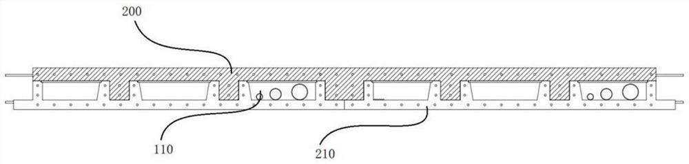
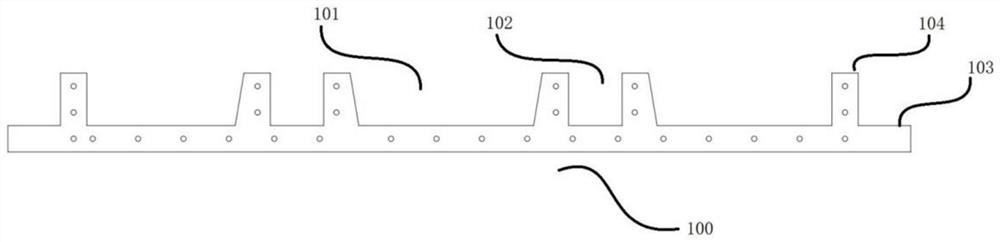
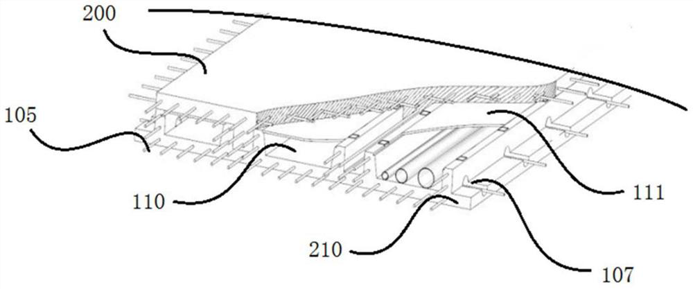
[0045] Such as Figure 1-Figure 4 A prefabricated multi-groove reinforced laminated floor slab is shown, including a form plate 210 and a cast-in-place concrete layer 200 poured on the form plate 210. The form plate 210 includes a bottom plate 100 and a reinforcing rib 104. The reinforcing rib 104 and the bottom plate 100 are Integral structure, the reinforcing ribs 104 are upwards straight to the bottom plate 100, structural intervals 102 and functional intervals 101 are formed between the reinforcing ribs 104, the functional intervals 101 and structural intervals 102 are distributed alternately, the functional intervals The upper end of the interval 101 is sealed with a cover plate 111 to form a cavity 110 or filled with functional materials. The bottom plate 100 has a pick-up edge 103, and there are butt joint reserved steel bars protruding from both sides of the bottom plate, and stressed steel bars 105 are evenly distributed inside the bottom plate. , the stressed steel b...

Embodiment 2

[0051] The difference from Embodiment 1 is that, as Figure 8-Figure 10 As shown, when the two ends of the base plate 10 are edge-sealed with reinforcing ribs, there is no overhanging edge. When the plurality of templates 21 are arranged horizontally, there is an interval between the outer edge reinforcing ribs 14 of each two base plates 10, and a hanging frame is installed in the interval. The mold 22 or the on-site mold support form the stressed rib beams between the formworks. The suspended mold 22 is bound with a stressed steel cage. The suspended mold 22 is suspended on the ribs 14 on both sides and parallel to the bottom plate 10. The ends are level with the two bottom plates 10. In addition, in this embodiment, the functional space 11 is filled with functional materials, which can be thermal insulation materials, sound insulation materials, and heat insulation materials. The hanging formwork is a permanent non-demolition bottom formwork and a temporary hanging formwork...

Embodiment 3

[0054] The difference between this embodiment and the first embodiment is that, if Figure 13-14 The surface of the reinforcing rib of the template shown in contact with the cast-in-place concrete layer is distributed with concave primary occlusal teeth 301 . When the bottom plate has a pick-up edge, secondary occlusal teeth 302 are distributed on the pick-up edge. When two adjacent panels are connected, the secondary occlusal teeth 302 on the pick-up edge correspond and are filled with cement. The concave area where the number of primary occlusal teeth / secondary occlusal teeth is greater than or equal to 1.


PUM


Abstract

The invention discloses an assembled multi-groove reinforced composite floor slab. The assembled multi-groove reinforced composite floor slab comprises a mould board and a cast-in-place concrete layer poured on the mould board, wherein the mould board comprises a bottom board and reinforcing ribs, the reinforcing ribs and the bottom board are of an integrated structure, the reinforcing ribs are upwards perpendicular to the bottom board, functional intervals and/or structural intervals are formed between the reinforcing ribs, the upper ends of the functional intervals are sealed with cover plates to form cavities or are filled with functional materials, stressed steel bars are uniformly distributed in the bottom plate, the stressed steel bars extend out of the bottom board, the cast-in-place concrete layer comprises a steel bar net formed by laying horizontal steel bars and vertical steel bars and concrete, and the steel bar net is fixedly connected with the reinforcing ribs. By adopting the floor slab structure comprising the template comprising the bottom board and the reinforcing ribs and the cast-in-place concrete layer poured on the mould board, the overall strength and bearing capacity of the composite floor slab can be enhanced, the overall rigidity of a traditional small-span composite floor slab can be improved, the slab bottom cracking and overall deformation in the production process are prevented, and the requirements of a larger-span assembled floor slab are met.

Description

technical field [0001] The invention relates to a reinforced laminated panel for an assembled passive house, in particular to an assembled multi-groove reinforced laminated floor slab. Background technique [0002] Prefabricated passive house is a brand-new concept of energy-saving buildings, which originated from low-energy buildings in Germany in the 1980s. Thermal insulation and air tightness minimize the building's heating and cooling needs. [0003] Prefabricated concrete structure (prefabricated concrete structure) is the abbreviation of prefabricated concrete structure, which is a concrete structure formed by assembling and connecting prefabricated components as the main stress components. Prefabricated reinforced concrete structure is one of the important directions for the development of my country's building structure. It is conducive to the development of my country's building industrialization, improving production efficiency and saving energy, developing green ...

Claims


Application Information

Patent Timeline
IPC IPC(8): E04B5/48
CPCE04B5/48
Inventor 王勇王伟
Owner 王勇
Why Eureka
Try Eureka