Linear motor and linear guiding apparatus

a linear guiding and motor technology, applied in the field of rod-type linear motors, can solve the problems of unsuitable gap between the polyphase coils, inability to realize the linear guiding apparatus having a large traveling range, and inability to keep the stationary rod 110/b>, etc., to achieve the effect of increasing the rigidity against the bending moment, increasing the span, and increasing the rigidity

Inactive Publication Date: 2005-12-20
THK CO LTD
View PDF7 Cites 20 Cited by
  • Summary
  • Abstract
  • Description
  • Claims
  • Application Information

AI Technical Summary

Benefits of technology

[0006]The present invention has been made in view of the aforementioned problems and the object of the present invention is to provide a rod type linear motor of which a rod-like member has increased rigidity against the bending moment, allowing the increase in span of the linear motor (moving distance of a movable member) and, in addition, which can obtain large thrust even when the width of the rod-like member is small and to provide a linear guiding apparatus using this linear motor as a driving means.

Problems solved by technology

There is a problem that, if the deflection is grown, the suitable gap between the polyphase coil 121 and the rod-like stationary member 110 can not be kept according to the travel of the movable member 120.
Accordingly, there is a problem that it is impossible to realize the linear guiding apparatus having a large traveling range.
However, in the linear guiding apparatus of this kind, there is a limitation on increase of the space between the rails so that the rod-like stationary member of the linear motor must be disposed in the limited width.
Therefore, there is a problem that large thrust can not be achieved due to the limitation on increase in diameter of the section of the cylindrical rod-like stationary member.

Method used


Image

  • Linear motor and linear guiding apparatus
  • Linear motor and linear guiding apparatus
  • Linear motor and linear guiding apparatus

Examples


Embodiment Construction

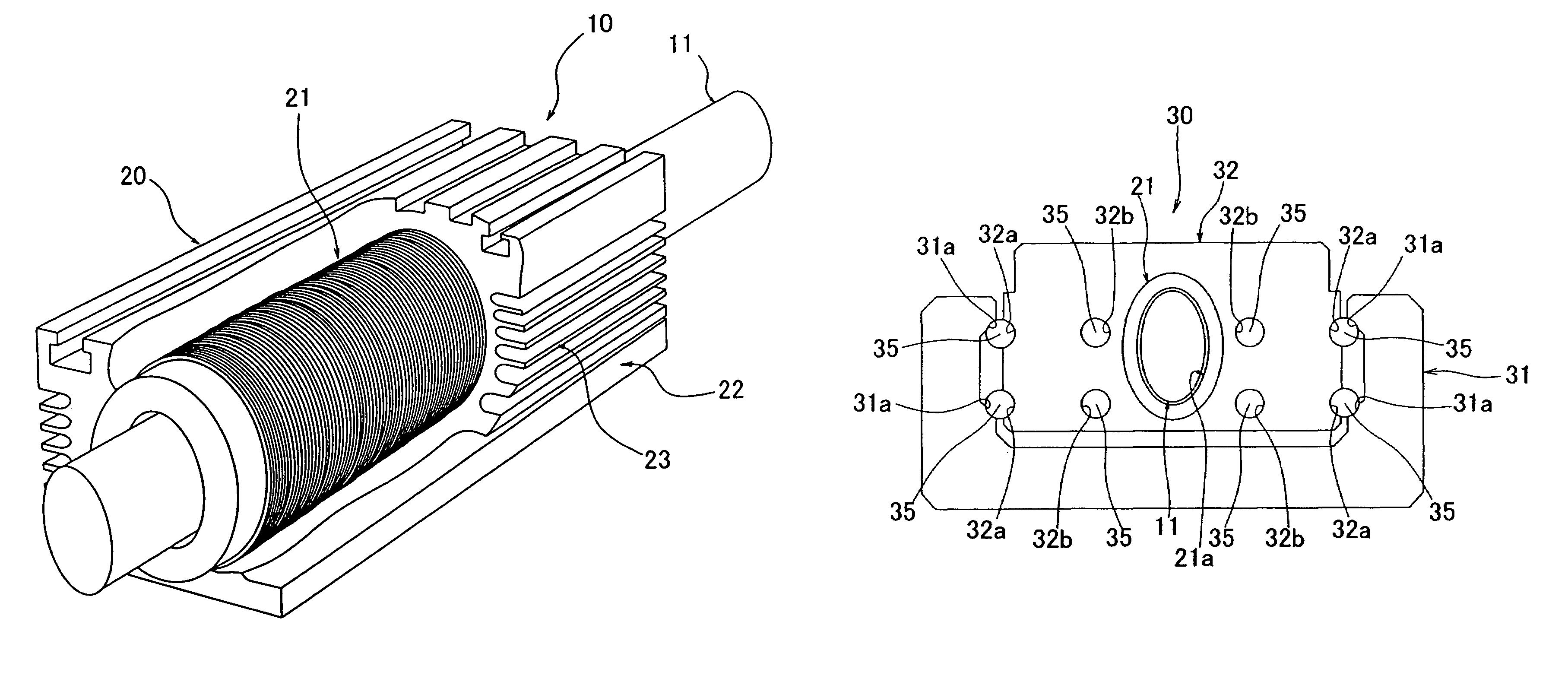
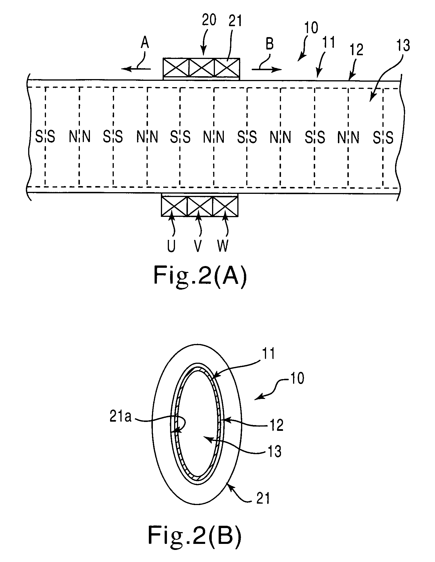
[0029]Hereinafter, embodiments of the present invention will be described with reference to the attached drawings. FIGS. 2(A) and 2(B) are schematic illustrations showing a structural example of a linear motor according to the present invention. A linear motor 10 comprises a rod-like stationary member 11 and a movable member 20. The rod-like stationary member 11 comprises a cylindrical body 12 having a substantially oval section and made of non-magnetic material (for example, stainless steel) and segment magnets 13 having a substantially oval plate shape which are accommodated and stacked in the axial direction in the cylindrical body 12 such that the same poles of the adjacent segment magnets 13 confront each other. The movable member 20 comprises a polyphase coil 21 (in the illustrated example, a three-phase coil consisting of phases U, V, and W) surrounding the rod-like stationary member 11.

[0030]The polyphase coil 21 is provided with a center bore 21a having a substantially oval...


PUM


Abstract

A linear motor is provided that includes a rod-like member having a cylindrical body made of a non-magnetic material and a plurality of plate-like segment magnets accommodated in the cylindrical body such that they are stacked in a longitudinal axial direction of the cylindrical body and a coil member having a polyphase coil. The rod-like member is arranged to extend through a center bore of the coil member. The rod-like member of the linear motor comprises the cylindrical body having a substantially oval or substantially rectangular section and the plurality of segment magnets having a substantially oval or substantially rectangular plate shape that are accommodated in the cylindrical body and stacked in the axial direction of the cylindrical body. The section of the center bore of the coil member is substantially oval or substantially rectangular corresponding to the shape of the section of the rod-like member.

Description

BACKGROUND OF THE INVENTION[0001]The present invention relates to a rod type linear motor comprising a coil member having a polyphase coil and a rod-like member having a cylindrical body made of a non-magnetic material and a plurality of plate-like segment magnets which are accommodated in the cylindrical body such that they are stacked in the axial direction of the cylindrical body, wherein a polyphase alternative current is applied to the polyphase coil of the coil member to produce a shifting magnetic field, thereby moving the rod-like member or the coil member. The present invention also relates to a linear guiding apparatus employing the linear motor as a driving means.[0002]FIGS. 1(A), 1(B) are illustrations showing a schematic structure of a conventional rod type linear motor of this kind. As illustrated, a linear motor 100 comprises a rod-like stationary member 110 and a movable member 120. The rod-like stationary member 110 comprises a cylindrical body 111 made of non-magne...

Claims


Application Information

Patent Timeline
Patent Type & Authority Patents(United States)
IPC IPC(8): B23Q1/58B23Q5/28H02K41/025H02K41/03
CPCB23Q1/58H02K41/03B23Q5/28G06Q50/04G06K19/0723
Inventor ASOU, TOSHIYUKIAIDA, TOMOYUKI
Owner THK CO LTD
Why Eureka
Try Eureka