Floor care appliance equipped with detachable power cord

Inactive Publication Date: 2007-04-05
GOGEL NATHAN A +1
View PDF0 Cites 103 Cited by
  • Summary
  • Abstract
  • Description
  • Claims
  • Application Information

AI Technical Summary

Benefits of technology

[0012] In accordance with yet another aspect of the present invention a method is provided for improving the versatility of a floor cleaning appliance for different user applications. Such a method includes the steps of equipping the floor care appliance with a detachable electric power cord and allowing a user to select

Problems solved by technology

Unfortunately, building code requirements relating to the placement of electrical wall outlets have varied over the years and continue to vary from place to place.
As a consequence, many have found the standard length electrical cord provided on an appliance to be insufficient to reach from an available electrical wall outlet

Method used


Image

  • Floor care appliance equipped with detachable power cord
  • Floor care appliance equipped with detachable power cord
  • Floor care appliance equipped with detachable power cord

Examples


Embodiment Construction

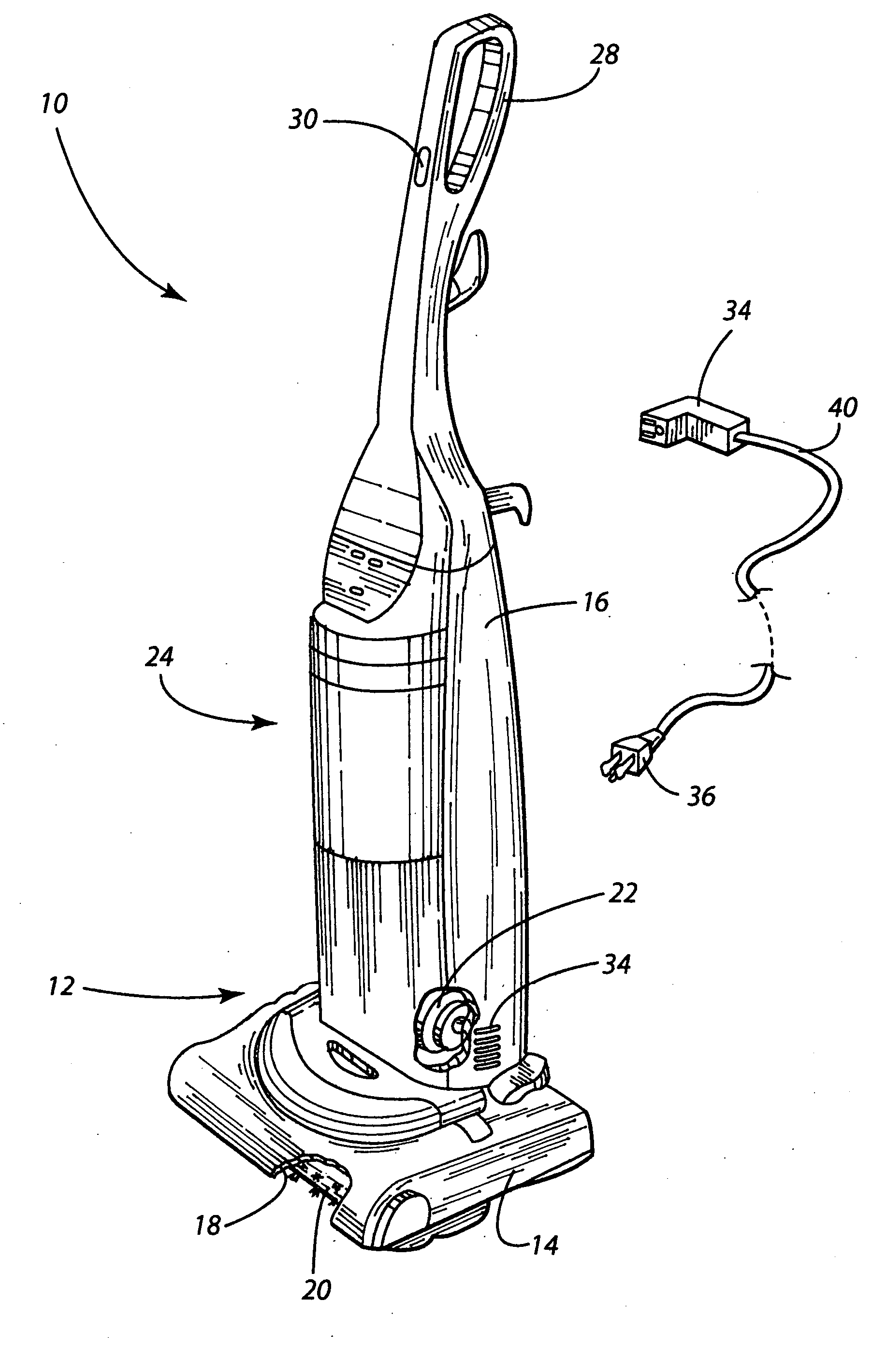
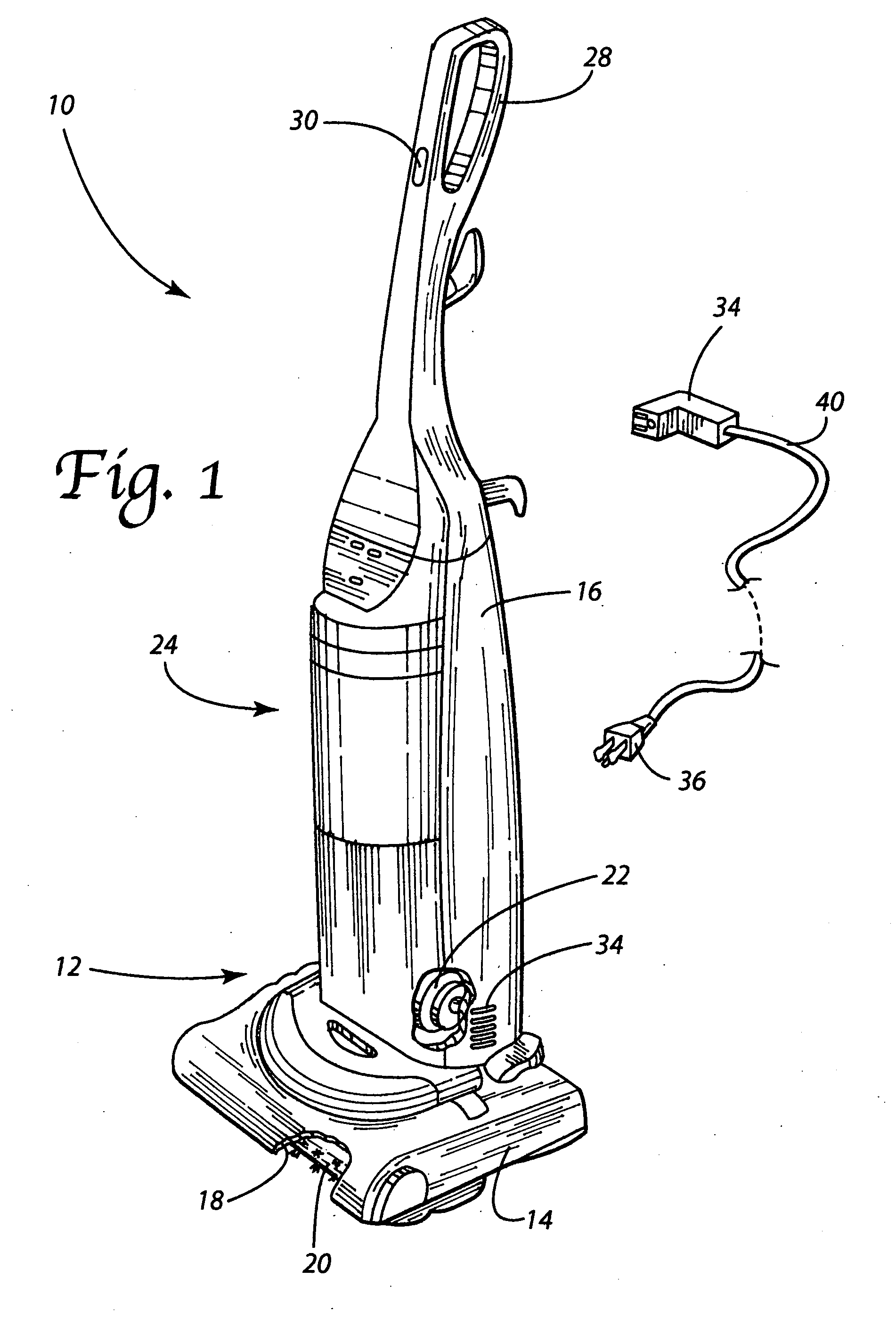
[0019] Reference is now made to FIG. 1 schematically illustrating the floor care or cleaning appliance 10 of the present invention. In the illustrated embodiment the appliance 10 takes the form of an upright vacuum cleaner. It should be appreciated, however, that this is for illustrative purposes only and that the present invention also includes other floor care or cleaning appliances such as extractors and canister vacuum cleaners.

[0020] As illustrated the appliance 10 includes a housing 12 comprising both a nozzle assembly 14 and a canister assembly 16. In the illustrated appliance 10, the canister assembly 16 is pivotally connected to the nozzle assembly 14. In a canister vacuum cleaner the nozzle assembly 14 and the canister assembly 16 would be separate components interconnected by a flexible hose for conveying air entrained with dirt between the nozzle assembly and the canister assembly.

[0021] As illustrated, the nozzle assembly 14 includes a suction inlet 18. In addition, a...


PUM


Abstract

A floor care appliance is equipped with a detachable power cord.

Description

[0001] This application claims the benefit of U.S. Provisional Patent Application Ser. No. 60 / 723,719 filed on 5 Oct. 2005.TECHNICAL FIELD [0002] The present invention relates generally to the floor care equipment field and, more particularly, to a floor care appliance equipped with a detachable electric power cord. BACKGROUND OF THE INVENTION [0003] Vacuum cleaners, extractors and other floor care appliances are commonly utilized in residential and commercial settings to clean dirt and debris from rugs, carpets, hardwood, tile, vinyl, linoleum and other floor covering materials. Such appliances are used in a multitude of locations and settings. While some are battery powered, most are powered with electricity via a standard electrical wall outlet such as provided under the National Electrical Code as published by the National Fire Protection Association and as outlined in the standards of the National Electrical Manufacturers Association (NEMA) or the American National Standards In...

Claims


Application Information

Patent Timeline
IPC IPC(8): H01R11/00
CPCH01R13/60
Inventor GOGEL, NATHAN A.KONDO, YASUSHI
Owner GOGEL NATHAN A
Why Eureka
Try Eureka