Sectional three-dimensional model

Inactive Publication Date: 2007-04-05
JEON DONG IN
View PDF7 Cites 15 Cited by
  • Summary
  • Abstract
  • Description
  • Claims
  • Application Information

AI Technical Summary

Benefits of technology

[0010] Therefore, the present invention has been made in view of the above problems, and it is an object of the present invention to provide a sectional three-dimensional model, which can be asse

Problems solved by technology

Currently commercialized three-dimensional models, however, have a problem in that the assembling of a model requires to combine a plurality of pieces having different shapes from one another, and therefore, may be impossible when losing only a part of the pieces.
In particular, since the sectional models are intended to be used by infants and children lacking in the concept of proper arrangement, the models are easy to fail to fulfill their assembling function due to the loss of their constituent pieces.
Disposal of these sectional models, which are no longer useful, results in economical waste.
Another problem of conventional sectional models is in that they are assembled mainly by adopting a two-dimensional connection, and therefore, it is impossible to assemble a model having a specific shape requiring a three-dimensional connection, such as for e

Method used


Image

  • Sectional three-dimensional model
  • Sectional three-dimensional model
  • Sectional three-dimensional model

Examples


first embodiment

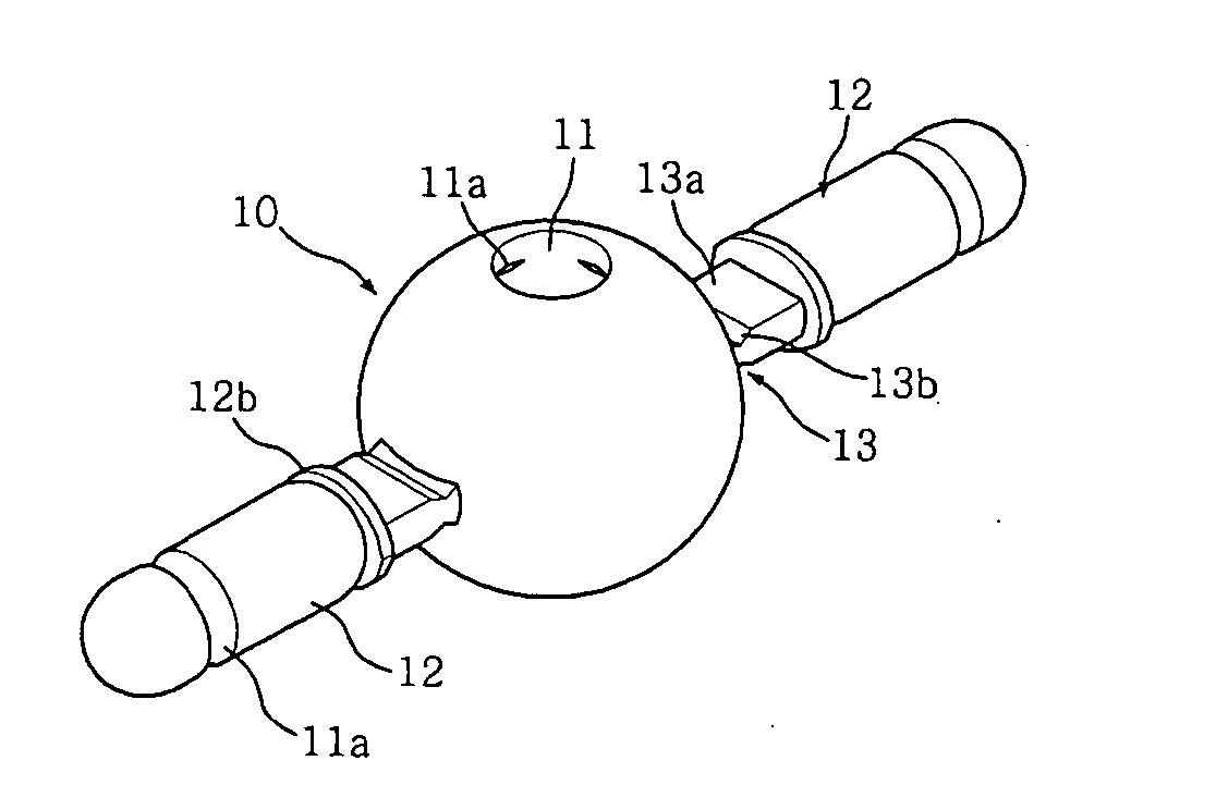
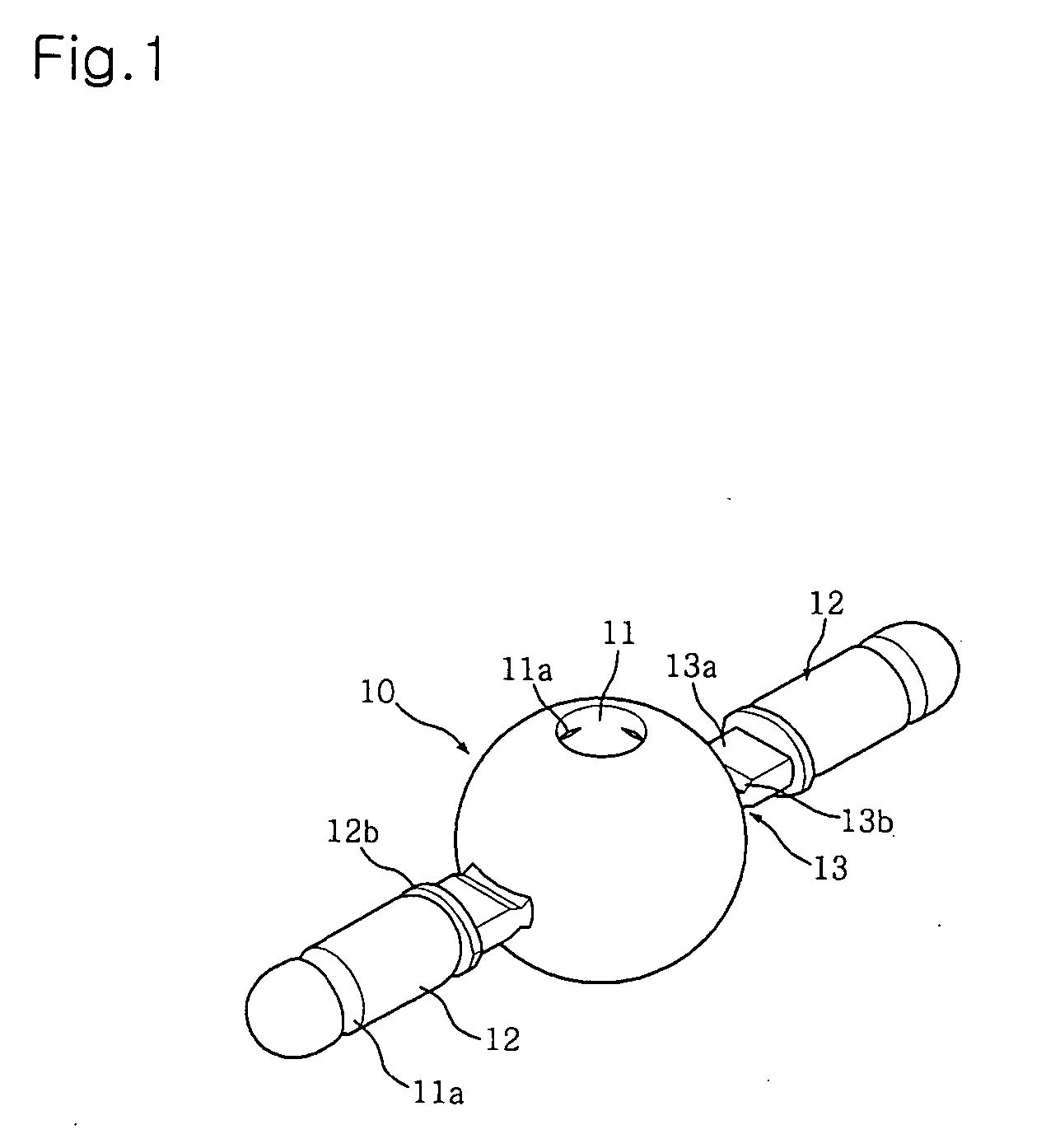
[0039]FIG. 1 is a perspective view illustrating one piece of a sectional three-dimensional model according to the present invention.

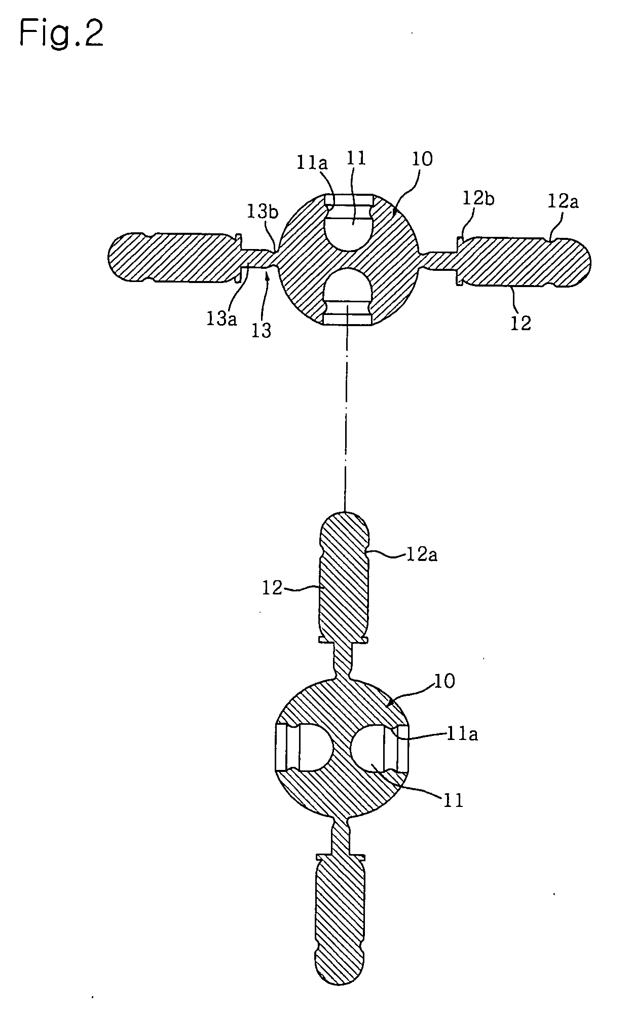
[0040] As shown in FIG. 1, the sectional three-dimensional model according to the first embodiment of the present invention includes a plurality of spherical pieces 10, and each spherical piece 10 has a pair of coupling recesses 11 and a plurality of coupling protrusions 12. The pair of coupling recesses 11 are symmetrically formed in the spherical piece 10 along the center axis of the spherical piece 10, and the plurality of coupling protrusions 12 are arranged in directions perpendicular to the coupling recesses 11. With this configuration, as the coupling protrusions 12 of one spherical piece 10 are selectively inserted into the coupling recesses 11 of another spherical piece 10, two or more spherical pieces 10 can be connected to one another.

[0041] Each coupling recess 11 of the spherical piece 10 has a semi-spherically dented bottom, and correspon...

second embodiment

[0049]FIG. 9 is a perspective view illustrating a connection pipe according to the present invention, which is partially cut-away. The connection pipe 30 has an inner diameter suitable to be fitted around the coupling protrusion 12 of the spherical piece 10. The connection pipe 30 is internally formed at opposite ends thereof with a pair of annular raised locking portions 30a each corresponding to the locking groove 12a of the associated coupling protrusion 12.

[0050] The connection pipe 30 has a pleated flexible portion 30b formed at approximately the center portion thereof. Providing the connection pipe 30 with the flexible portion 30b allows free bending of the connection pipe 30, and thus, is advantageous to assemble a curved model. Furthermore, the connection pipe 30 having the flexible portion 30b is length adjustable. Accordingly, for example, the length adjustable connection pipe 30 can be used to constitute a longer length side of a right-angled triangle connecting the remai...

third embodiment

[0051]FIGS. 10A to 10C illustrate a connection rod according to the present invention, FIG. 10A being a front view, FIG. 10B being an enlarged view of the circle “A” of FIG. 10A, and FIG. 10C being a sectional view taken along the line B-B of FIG. 10B.

[0052] As shown in FIGS. 10A to 10C, the connection rod 20 is shaped as an elongated bar having a circular cross section. The connection rod 20 has protuberances 21 formed at opposite ends thereof. Each protuberance 21 has the same semi-spherical shape as the end of the coupling protrusion 12 of the spherical pieces 10, so as to be inserted into the coupling recess 11 of the spherical piece 10. To allow the protuberance 21 of the connection rod 20 to be inserted into the coupling recess 11 of the spherical piece 10 without the risk of unintentional separation thereof, the protuberance 21 is formed with an annular locking groove 21a for the engagement of the raised locking portion 11a formed at the inner circumference of the associated ...


PUM


Abstract

Disclosed herein is a sectional three-dimensional model, which can be assembled by use of an independent single type of pieces without requiring several kinds of pieces having different shapes from one another, and achieve a three-dimensional connection of the pieces. The sectional three-dimensional model includes a plurality of spherical pieces, and each spherical piece includes a pair of coupling recesses symmetrically formed in the spherical piece along a center axis of the spherical piece, and a plurality of coupling protrusions integrally formed at an outer surface of the spherical piece to be arranged in directions perpendicular to the coupling recesses, thereby allowing the plurality of spherical pieces to be connected to one another via insertion of the coupling protrusions into the coupling recesses.

Description

BACKGROUND OF THE INVENTION [0001] 1. Field of the Invention [0002] The present invention relates to a sectional three-dimensional model, and more particularly, to a sectional three-dimensional model, which can be assembled by use of an independent single shape of pieces without requiring several kinds of pieces having different shapes from one another, and achieve a three-dimensional connection of the pieces. [0003] 2. Description of the Related Art [0004] Generally, sectional three-dimensional models are assembled to have a desired shape by combining a plurality of kinds of pieces having different shapes from one another. The sectional three-dimension models are utilized mainly as educational toys for infants and children. [0005] Currently commercialized three-dimensional models, however, have a problem in that the assembling of a model requires to combine a plurality of pieces having different shapes from one another, and therefore, may be impossible when losing only a part of th...

Claims


Application Information

Patent Timeline
IPC IPC(8): A63H33/12
CPCA63H33/065A63H33/084A63H33/08G09B1/06G09B19/10
Inventor JEON, DONG-INPARK, SUN-AH
Owner JEON DONG IN
Why Eureka
Try Eureka