
Fastener installation system

a technology of installation system and fastener, which is applied in the direction of fastening means, mechanical equipment, manufacturing tools, etc., can solve the problems of insufficient reliability of prior art blind rivet installation tools for industrial applications, inconvenient installation of blind rivets, and inefficient industrial environmen

Inactive Publication Date: 2007-04-12
FULBRIGHT DAVID J
View PDF35 Cites 9 Cited by
  • Summary
  • Abstract
  • Description
  • Claims
  • Application Information

AI Technical Summary

Benefits of technology

The patent describes a blind fastener installation tool that allows for the blind installation of a series of fasteners. The tool includes a structural housing with a fastener delivery assembly, a fastener installation assembly, and a pull rod assembly. The tool also has a nose assembly for securing the position of a fastener during installation. Additionally, there is an optional fastener delivery assembly for securely placing each fastener in succession. The tool can be used in a clip-fed or blowline-fed system for fastener delivery. The technical effects of this tool include improved efficiency and accuracy in fastener installation, reduced labor costs, and improved safety during construction.

Problems solved by technology

However, the vast majority of prior art designs have suffered from one or more important disadvantages.
First, the vast majority of prior art designs impart recoil to the operator upon rivet installation.
Second, the vast majority of prior arts designs are manually loaded, which is extremely inefficient in an industrial environment.
Third, most prior art blind rivet installation tools are insufficiently reliable for industrial applications.
Fourth, few, if any, prior art designs were designed to operate in multiple environments.
Fifth, most prior art designs are noisy, contributing to a hostile work environment.

Method used


Image

  • Fastener installation system
  • Fastener installation system
  • Fastener installation system

Examples


Embodiment Construction

[0049] This application is a continuation-in-part of, and claims the benefit of, and incorporates by reference the entirety of, three (3) prior patent applications.

[0050] This application incorporates the entirety of U.S. Provisional Application No. 60 / 536,593, filed Jan. 15, 2004 (entitled “A Fastener Installation System”), by reference, and, herein, whenever referenced, said provisional patent application will commonly be referred to as the “fastener installation system provisional patent application.”

[0051] This application also incorporates the entirety of U.S. Provisional Application No. 60 / 604,648, filed Aug. 26, 2004 (entitled “Improvements to a Fastener Installation System”), by reference, and, herein, whenever referenced, said provisional patent application will commonly be referred to as the “fastener installation system improvements provisional patent application.”

[0052] This application also incorporates the entirety of U.S. Nonprovisional application Ser. No. 11 / 035,00...


PUM

PropertyMeasurementUnit
angleaaaaaaaaaa
speedaaaaaaaaaa
speedaaaaaaaaaa

Abstract

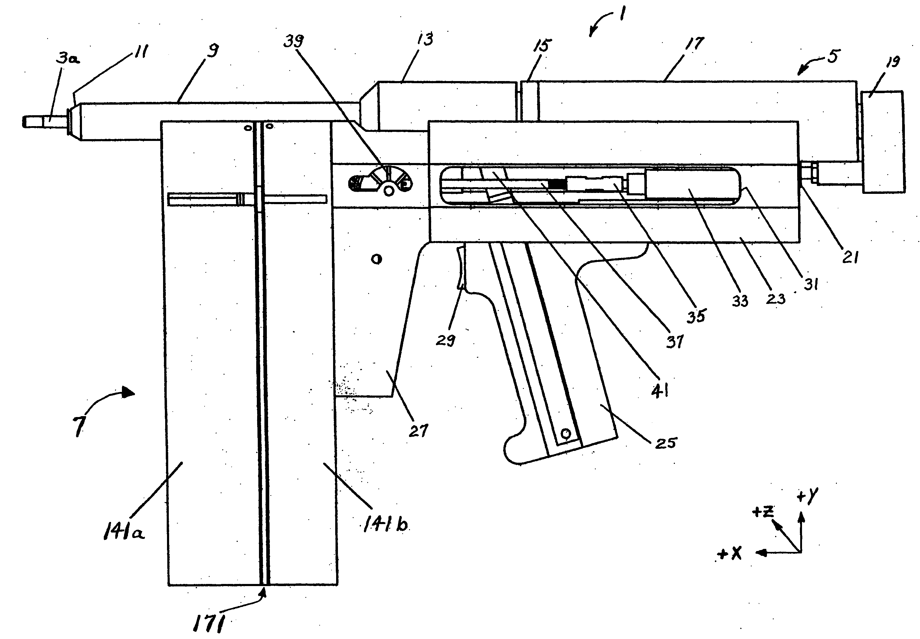
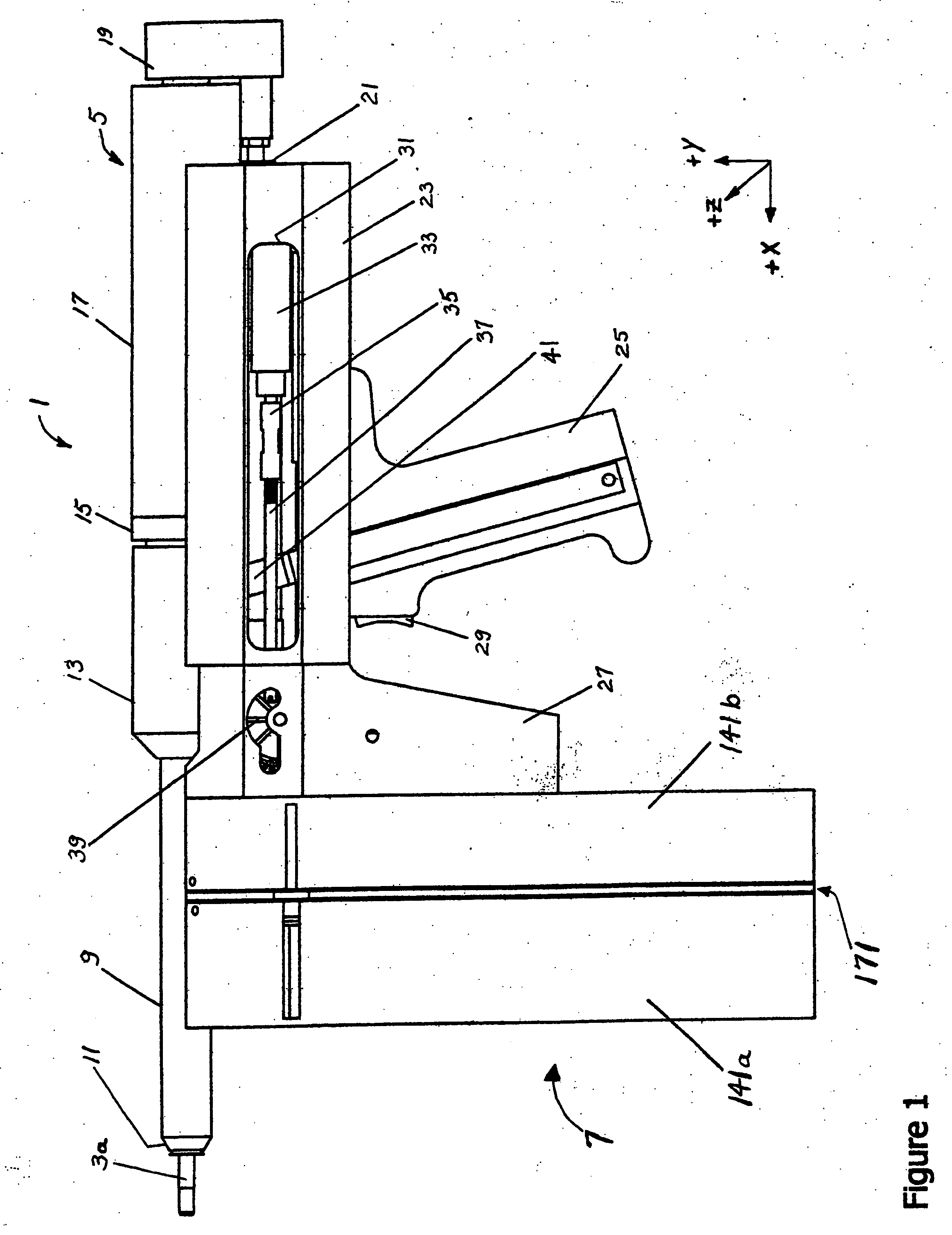
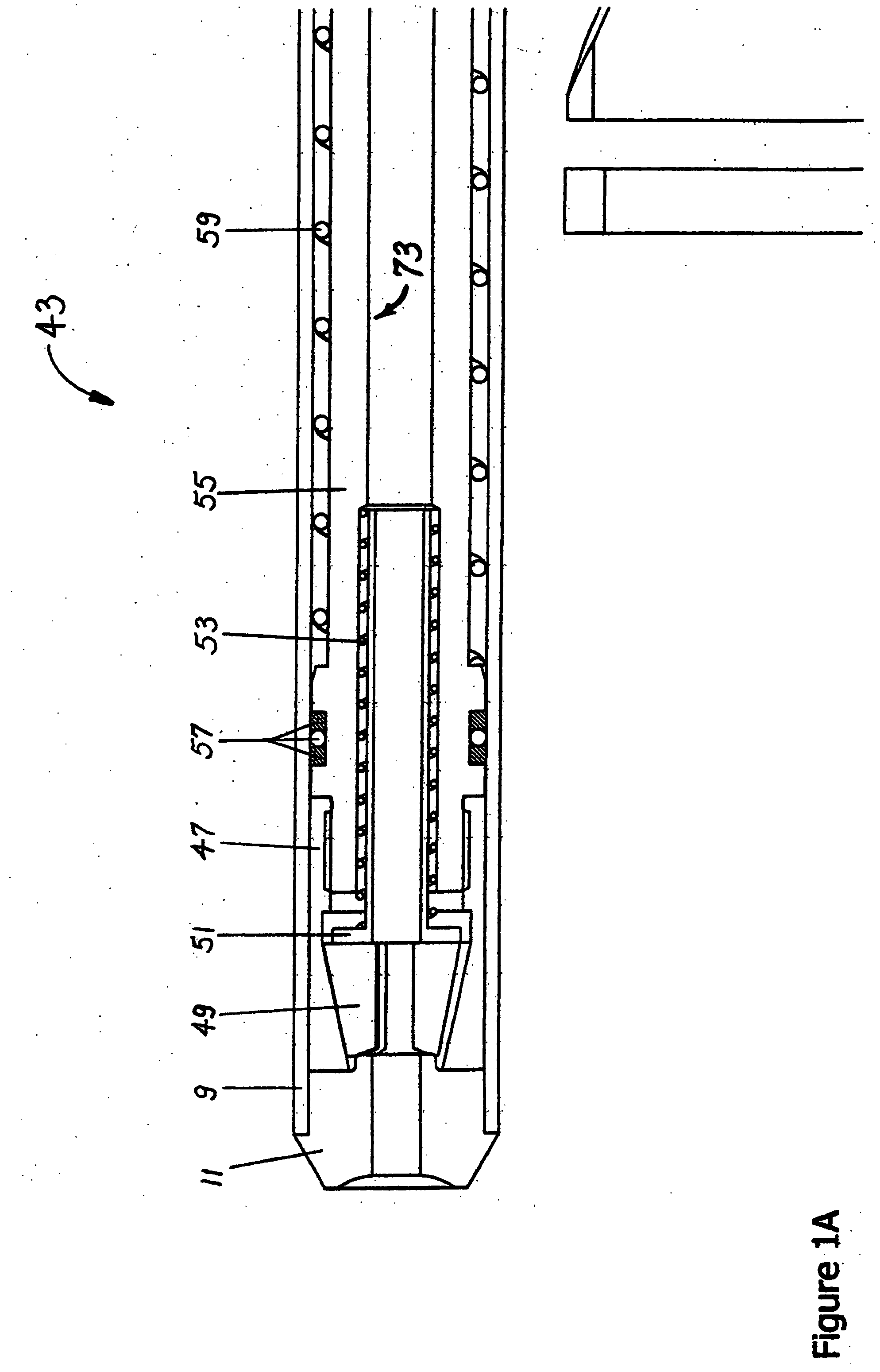
A blind fastener installation tool which accomplishes the blind installation of a series of fasteners is described in detail in this specification. The blind fastener installation tool comprises a structural housing which features a means for securing a fastener installation assembly in position relative to said structural housing during the blind installation of a fastener; and a means for reciprocating said fastener installation assembly relative to said structural housing at the conclusion of a cyclic blowline-fed or clip-fed blind installation of a fastener. The blind fastener installation tool also comprises a fastener installation assembly comprising (1) a pull rod assembly comprising means for pulling a first portion of a fastener; (2) an annular, piston-actuated, direct action, piston-decoupled pull rod actuation assembly to translate the pull rod assembly relative to said fastener installation assembly when said fastener installation assembly is secured at a fastener installation assembly fastener installation position, thereby pulling said first portion of said fastener until blind installation of said fastener is complete; and (3) a nose assembly comprising (3a) a fastener receptacle for securing the position of a fastener relative to said nose assembly during blind installation of said fastener; and (3b) one or more optional pull rod translation dampening assemblies to smoothly and effectually dampen the sudden translation of said pull rod assembly after pintail break during blind installation of a pintail-break—type fastener. The blind fastener installation tool also comprises an optional fastener delivery assembly, said optional fastener delivery assembly constituting: (1) a clip-fed fastener delivery system; or (2) a blowline-fed fastener delivery system.

Description

CROSS-REFERENCE TO RELATED APPLICATIONS [0001] This application is a continuation-in-part of, and claims the benefit of, and incorporates by reference the entirety of, the following applications: [0002] U.S. Provisional Application No. 60 / 536,593, filed Jan. 15, 2004 (entitled “A Fastener Installation System”). [0003] U.S. Provisional Application No. 60 / 604,648, filed Aug. 26, 2004 (entitled “Improvements to a Fastener Installation System”). [0004] U.S. Nonprovisional Application No. 11 / 035,009, filed Jan. 13, 2005 (entitled “A Fastener Installation System”).BACKGROUND OF THE INVENTION [0005] Blind rivet installation tools have been in existence for many years. However, the vast majority of prior art designs have suffered from one or more important disadvantages. [0006] First, the vast majority of prior art designs impart recoil to the operator upon rivet installation. Second, the vast majority of prior arts designs are manually loaded, which is extremely inefficient in an industria...

Claims


Application Information

Patent Timeline
Patent Type & Authority Applications(United States)
IPC IPC(8): B21D39/00B21J15/02B21J15/04B21J15/06B21J15/22B21J15/28B21J15/34B23Q7/10F16B21/18
CPCB21J15/043Y10T29/53752B21J15/22B21J15/28B21J15/285B21J15/32Y10T29/5118Y10T29/53739Y10T29/53487Y10T29/49954Y10T29/53522Y10T29/49956Y10T29/5377Y10T29/49943Y10T29/53496Y10T29/5373Y10T29/53513B21J15/105
Inventor FULBRIGHT, DAVID J.
Owner FULBRIGHT DAVID J
Learn More