
Outdoor canopy

a canopy and outdoor technology, applied in the field of canopy, can solve the problems of poor wind-proof arrangement of the conventional canopy, difficult assembly and disassembly of the most conventional canopy, and poor performance of the conventional canopy arrangement, so as to achieve convenient installation and effective ventilation

Active Publication Date: 2007-04-12
MA
View PDF25 Cites 17 Cited by
  • Summary
  • Abstract
  • Description
  • Claims
  • Application Information

AI Technical Summary

Benefits of technology

[0009] A main object of the present invention is to provide an outdoor canopy for a vehicle which comprises a ventilation arrangement which is capable of providing effective ventilation within the canopy, and is easy to install for convenient outdoor use.
[0010] Another object of the present invention is to provide an outdoor canopy comprising a ventilation arrangement which is capable of selectively providing effective ventilation while ensuring that the users' privacy is not thereby compromised.
[0011] Another object of the present invention is to provide an outdoor canopy which comprises a plurality of adjustable supporting legs for optimally standing on an uneven ground surface. In other words, the present invention is optimal for use in outdoor environment where the ground on which the outdoor canopy stands is usually uneven.
[0012] Another object of the present invention is to provide an outdoor canopy which mainly utilizes detachable connection between a canopy frame and the canopy fabric so as to minimize the time of assembling and disassembling of the present invention. Since the mechanical components of the outdoor canopy can be easily attached and detached, the outdoor canopy can therefore be easily transported and carried.
[0013] Another object of the present invention is to provide an outdoor canopy which does not involve complicated or expensive mechanical components so as to minimize the manufacturing of the present invention.
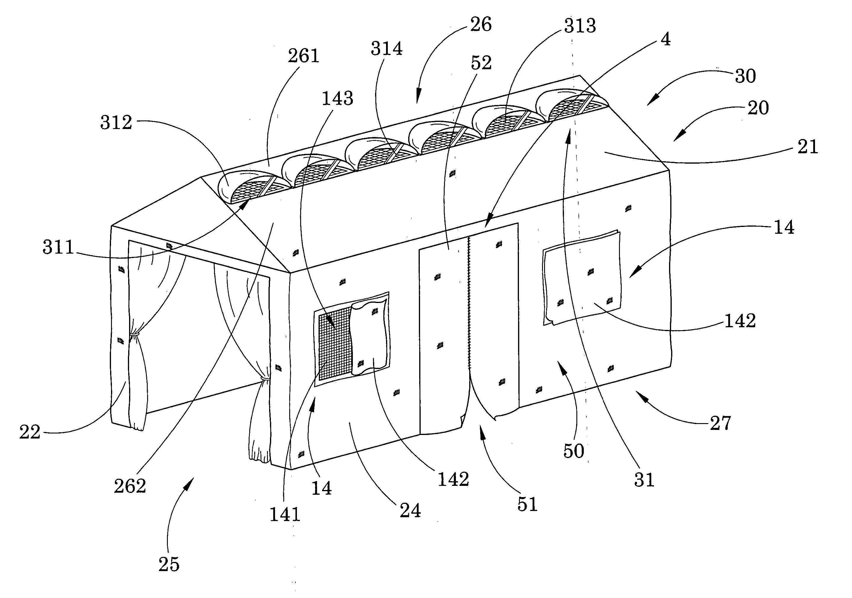
[0017] a ventilation arrangement comprising at least a side window for enhance an air ventilation of the canopy shelter, wherein the side window comprises a window screen formed at one of the sidewalls of the canopy fabric for allowing air circulation within the canopy area and a window blind overlappingly mounted on the respective sidewall in a foldable manner to selectively enclose the window screen, such that window blind is folded to enclose the window screen for preventing dust and rain entering into the canopy area and is folded to expose the window screen for allowing air circulating within the canopy area.

Problems solved by technology

Although more and more different kinds of functions and shapes being designed by inventor on canopies, there exist several disadvantages for conventional canopies.
First, the function of the wind-proof arrangement in conventional canopy is not good.
Second, because the height of the canopy can not be adjusted, it is not convenient for people to use.
Third, most conventional canopies do not have an independent lighting system so that people may not conduct social activities in the canopies during night time or in a dark environment.
There are other problems.
As a matter of fact, most conventional canopies are difficult to assemble and disassemble.
This may in part due to the fact that most conventional canopies are designed for use in outdoor environment, where strong wind and adverse weather condition may be prevalent.
Very often, this means that an inflexible mounting mechanism is employed.
The problem with this feature is that while windows may provide ventilation for the canopy, they do so by sacrificing the privacy of the people staying within the canopy.
More specifically, conventional canopies do not usually have some sorts shading for allowing the users to selectively cover up the window so that they will find that the provision of windows may actually bring inconvenience to them.
Moreover, for conventional car canopies, there exists a problem that there are inadequate canopy doors for users.
Very often, however, the users will find that it is very difficult for them to reach the door of the vehicle through the main door opening because when a vehicle has parked within the canopy, there may have very little space left for the users.

Method used


Image

  • Outdoor canopy
  • Outdoor canopy
  • Outdoor canopy

Examples


Embodiment Construction

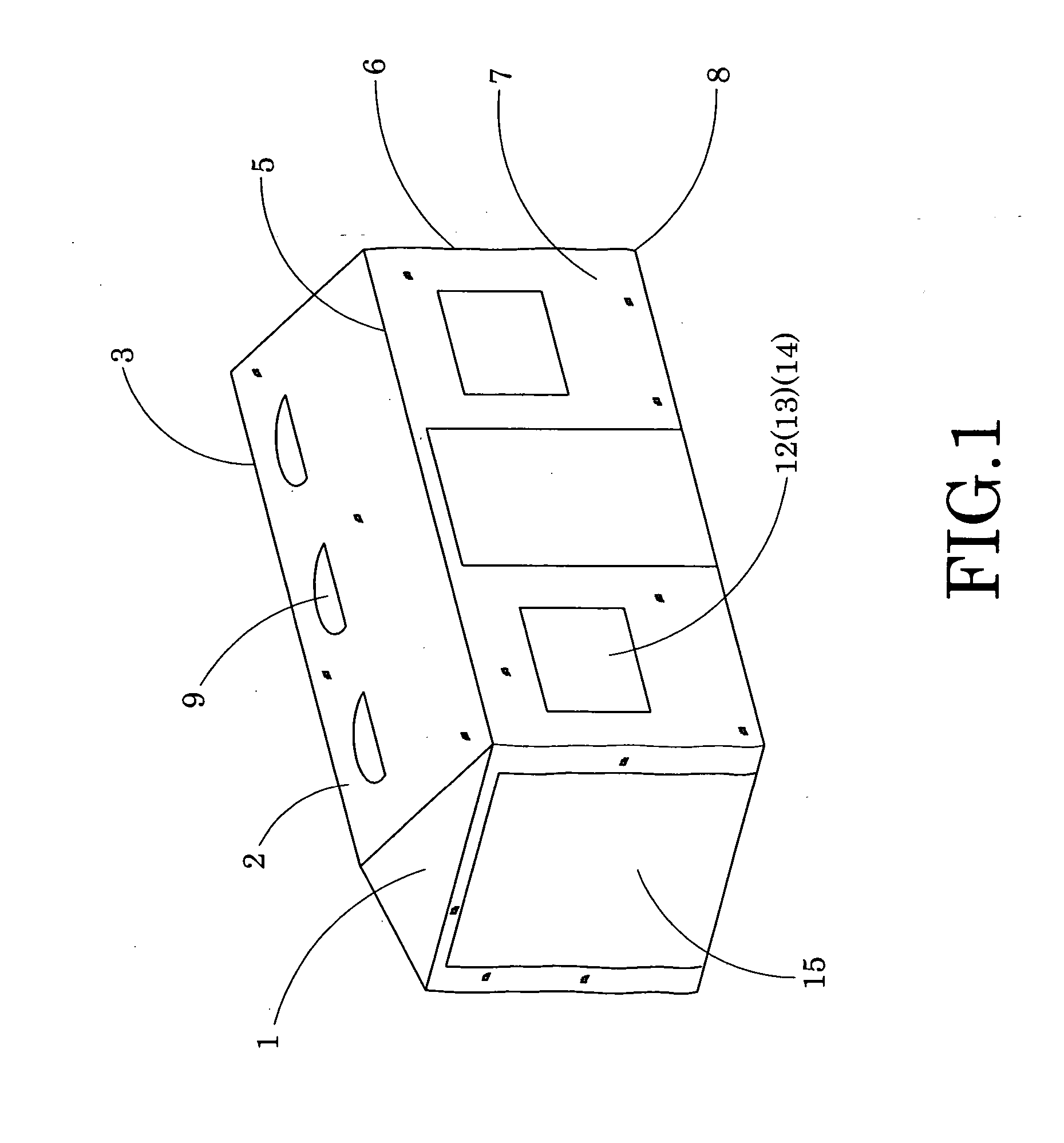
[0038] Referring to FIG. 1 of the drawings, a canopy, such as an outdoor canopy, according to a preferred embodiment of the present invention is illustrated, in which the canopy comprises a first fabric panel 1 and a second fabric panel 1, a top canopy 2, a roof frame 3, a side wall 4, a horizontal bar 5, a legs frame 6, a side fabric panel 7, and a mounted plate 8.

[0039] A first fabric panel 1 means the front side fabric panel of the canopy, and a second fabric panel 1 means the back side fabric panel of the canopy.

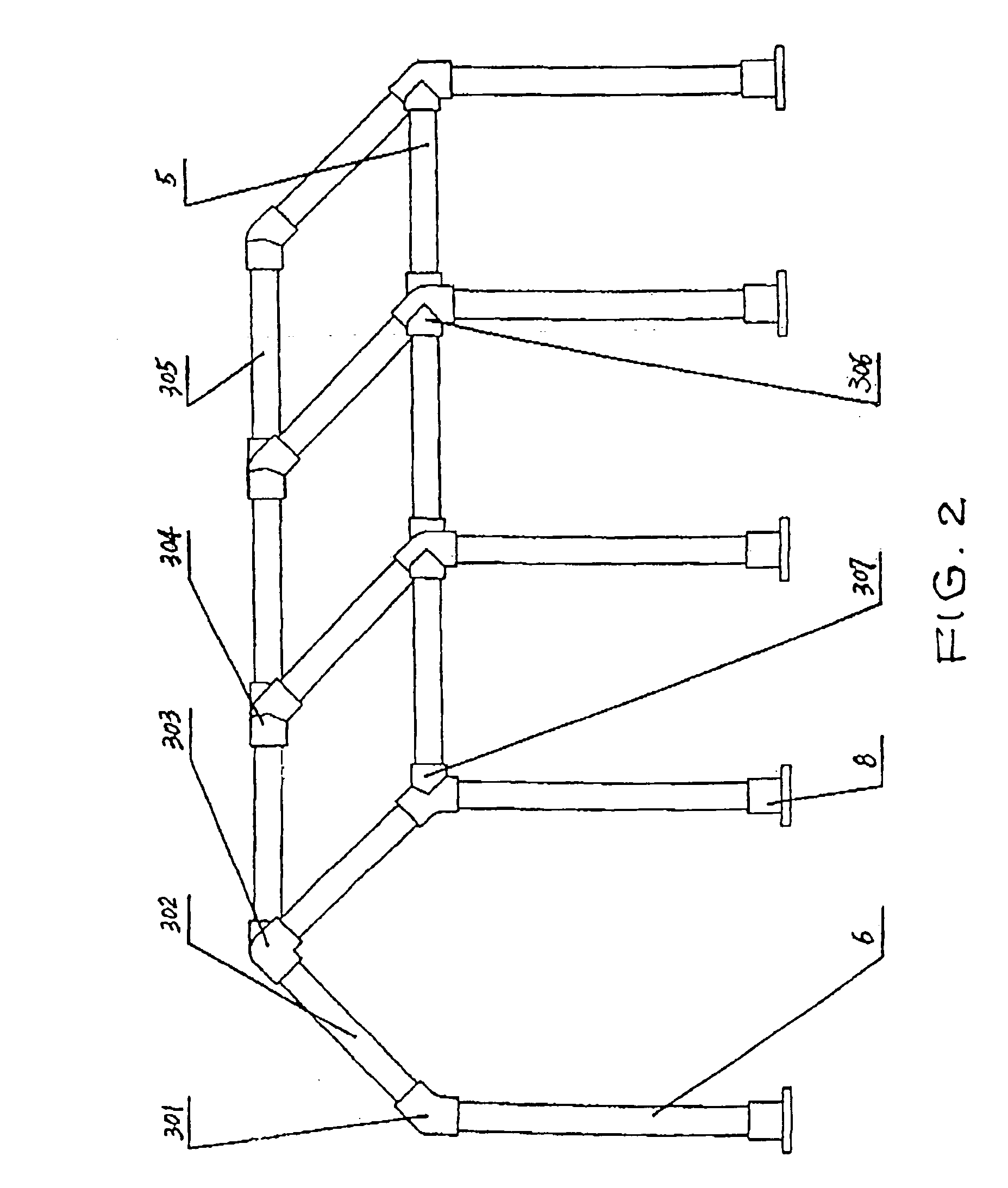
[0040] A roof frame 3 provided on top of the legs frame, wherein the roof frame 3 comprises a horizontal bar 305 and a plurality of inclined bars 302 spacedly, inclinedly and downwardly extended from the horizontal bar to connect with the legs frame 6.

[0041] A legs frame 6 which comprises a plurality of adjustable supporting legs 61 spacedly and upwardly extended from a ground surface to define a canopy area within the supporting legs 61, wherein a height of each of t...


PUM


Abstract

An outdoor canopy includes a canopy frame, a canopy shelter and a side entrance arrangement. The canopy frame includes a roof frame and a legs frame downwardly extended from the roof frame to form a canopy area. The canopy shelter, which is made of waterproof fabric, is detachably fastening at the canopy frame to define a ceiling wall, a front wall, a rear wall and two sidewalls for enclosing the canopy area therewithin. The side entrance arrangement is formed on one of the sidewalls of the canopy shelter for a user to gain entry to and exit the canopy area without having to pass through the front entrance, wherein the side entrance arrangement contains a side entrance opening formed on the corresponding sidewall of the canopy shelter, and comprise at least one entrance fabric operatively mounted on the corresponding sidewall.

Description

CROSS REFERENCE OF RELATED APPLICATION [0001] This application is a continuation-in-part of a utility application having an application Ser. No. 11 / 583,247, and a filing date of 18th Oct., 2006.BACKGROUND OF THE PRESENT INVENTION [0002] 1. Field of Invention [0003] The present invention relates to a canopy, and more particularly to a canopy for a vehicle which comprises a ventilation arrangement which is capable of providing effective ventilation within the canopy, and is easy to install for convenient outdoor use. [0004] 2. Description of Related Arts [0005] A canopy for a vehicle provides users with a specific place to avoid direct exposure from strong sunshine, such as in villas, beaches, hotels, apartments etc. Although more and more different kinds of functions and shapes being designed by inventor on canopies, there exist several disadvantages for conventional canopies. First, the function of the wind-proof arrangement in conventional canopy is not good. Especially when we use...

Claims


Application Information

Patent Timeline
Patent Type & Authority Applications(United States)
IPC IPC(8): E04H15/00
CPCE04H15/16E04H15/32E04H15/44
Inventor LI, WANDA YING
Owner MA
Learn More