Position sensitive shock absorber

US20070080515A1Active Publication Date: 2007-04-12SPECIALIZED BICYCLE COMPONENTS INC

Image

  • Position sensitive shock absorber
  • Position sensitive shock absorber
  • Position sensitive shock absorber

Examples


Embodiment Construction

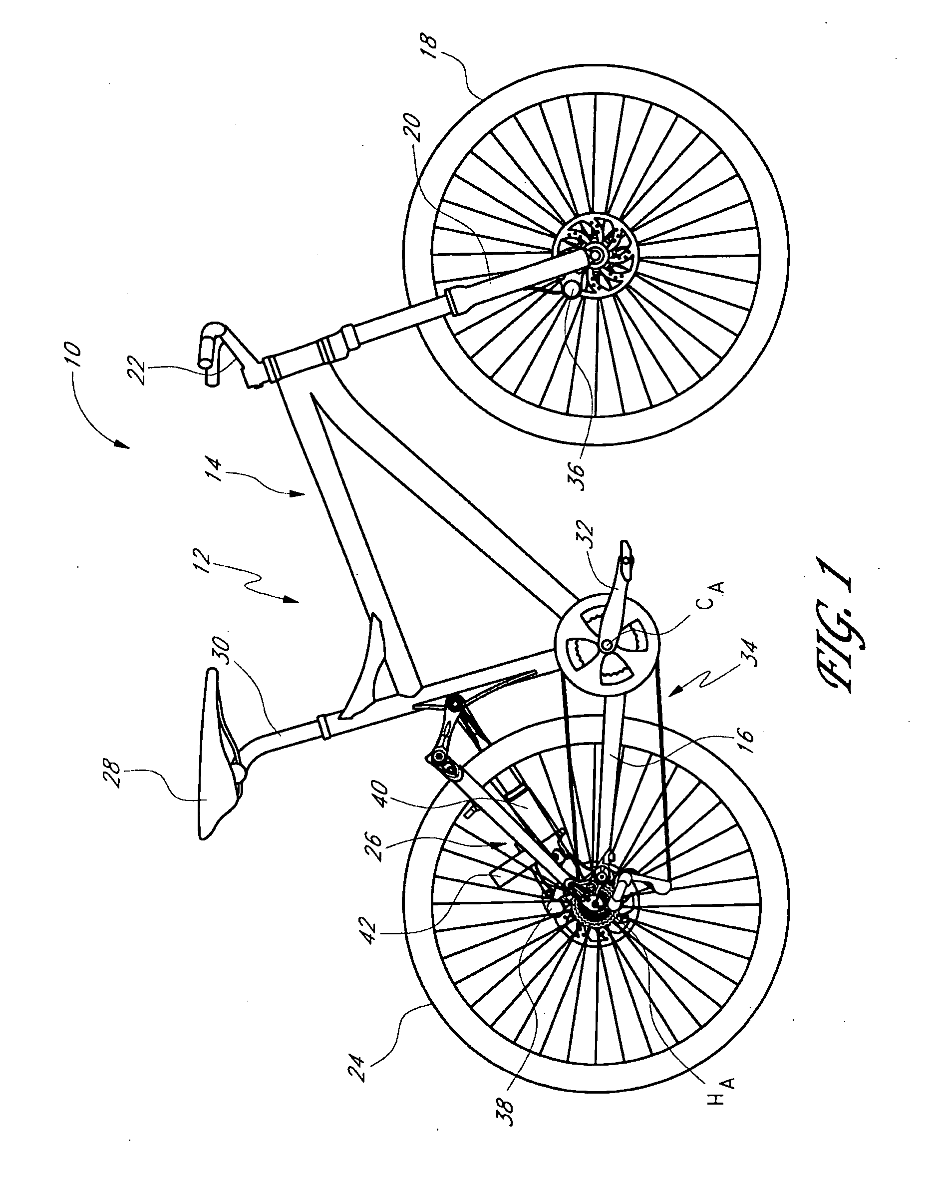
[0037]FIG. 1 illustrates an off-road bicycle, or mountain bike 10, including a preferred embodiment of a rear suspension assembly, or shock absorber. The bicycle 10 is described herein with reference to a coordinate system wherein a longitudinal axis extends from a forward end to a rearward end of the bicycle 10. A vertical, central plane generally bisects the bicycle 10 and contains the longitudinal axis. A lateral axis extends normal to the longitudinal axis and lies within a horizontal plane. In addition, relative heights are generally expressed as elevations relative to a horizontal surface on which the bicycle 10 is supported in an upright position. The above-described coordinate system is provided for the convenience of describing the bicycle illustrated in FIGS. 1 and 5, and is not intended to limit the scope of the present invention. In addition, certain features and components of the bicycle may be described in terms of relative positions or directions within the particular...


PUM


Abstract

A shock absorber includes a tube and a piston rod carrying a piston. The piston is configured for reciprocal movement within the tube. A floating piston, or other type of accumulator, is configured to move to accommodate fluid displaced due to successive portions of the piston rod entering the tube during compression of the shock absorber. The shock absorber includes a valve mechanism that utilizes the movement of the floating piston to move the valve between a first and second position, which preferably are open and closed positions.

Description

CROSS-REFERENCE TO RELATED APPLICATIONS [0001] This application is related to, and claims priority from, U.S. Provisional Patent Application No. 60 / 709,206, filed Aug. 18, 2005.INCORPORATION BY REFERENCE [0002] The entirety of U.S. Provisional Patent Application No. 60 / 709,206, filed Aug. 18, 2005, is expressly incorporated by reference herein and made a part of the present specification. BACKGROUND OF THE INVENTION [0003] 1. Field of the Invention [0004] The present invention generally relates to vehicle suspension systems. More specifically, the present invention relates to an improved shock absorber system to be incorporated into the suspension system of a vehicle, such as a bicycle. [0005] 2. Description of the Related Art [0006] Bicycles intended for off-road use, i.e., mountain bikes, commonly include a suspension assembly operably positioned between the front and / or rear wheels of the bicycle and the frame of the bicycle. The suspension assembly typically includes a shock abs...

Claims


Application Information

Patent Timeline
12 Apr 2007
Publication
US20070080515A1
IPC
B62K17/00
CPC
B62K25/04; B62K25/08; B62K25/286; B62K2025/048; F16F9/065; F16F9/067; F16F9/48; F16F9/486
Inventors
MCANDREWS, MICHAEL