Locking structure of tray of vehicle

Inactive Publication Date: 2007-04-12
HYUNDAI MOBIS CO LTD
View PDF15 Cites 14 Cited by
  • Summary
  • Abstract
  • Description
  • Claims
  • Application Information

AI Technical Summary

Benefits of technology

[0023] The button of the locking part is pulled forward to open the door so that the locking

Problems solved by technology

However, when shock is applied to the instrument panel in which the tray is installed, th

Method used


Image

  • Locking structure of tray of vehicle
  • Locking structure of tray of vehicle
  • Locking structure of tray of vehicle

Examples


Embodiment Construction

[0032] Hereinafter, the preferred embodiment of the tray locking structure of a vehicle according to the present invention will be described in detail with reference to the accompanying drawings.

[0033] The preferred embodiments will be not described to limit the scope of the present invention, but as examples, and it could be understood that there are several embodiments that may be implemented in the spirit of the present invention.

[0034]FIG. 4 is a schematic perspective view illustrating a button pulled forward to open a door according to a preferred embodiment of the present invention FIG. 5 is a view illustrating a locker in the closed state of a tray in FIG. 4, FIG. 6 is a view illustrating the button pulled down in the state shown in FIG. 4, and FIG. 7 is a view illustrating an assembly of die button and a locking body according to the preferred embodiment of the present invention.

[0035] As show in the drawings, in an inner panel of a vehicle, particularly in the upper side...


PUM


Abstract

A tray locking structure of a vehicle is disclosed. The structure includes a housing installed in an inner panel of the vehicle, having an accommodating room, an installation recess formed in the front side thereof, and a locking bar for crossing the locking recess, a door hinged to the rear side of the housing that can move up and down to thus open and close the door, and a locking part installed in the front side of the door, having a lower end locked by the locking bar, and an upper end pulled forward to release the locking part from the locking bar. The button of the locking part is pulled forward to open the door so that the locking part is not released from the locking state due to external shock so as to prevent accident.

Description

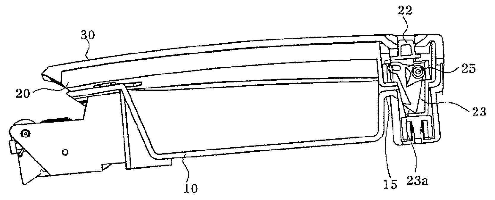
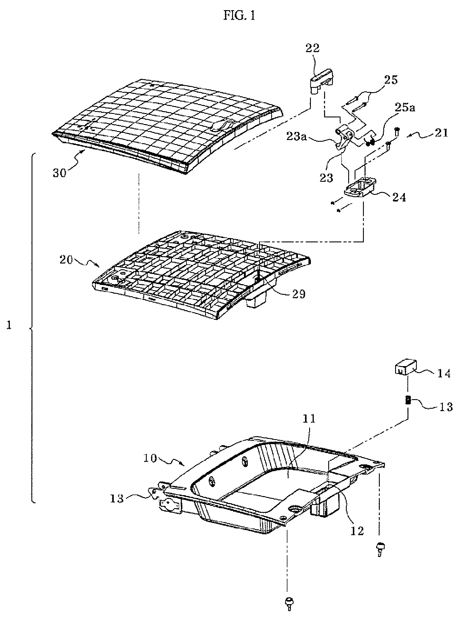
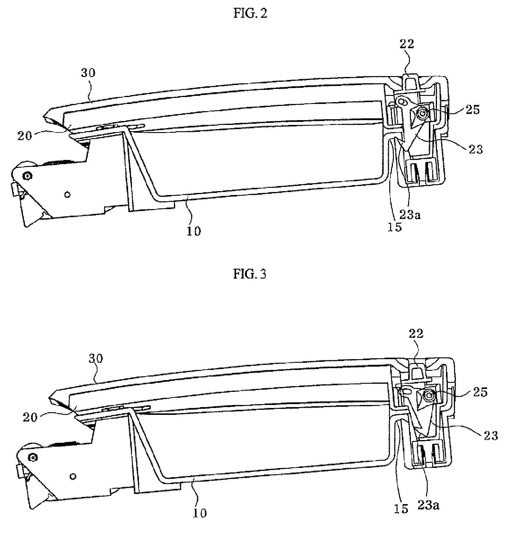
BACKGROUND OF THE INVENTION [0001] 1. Field of the Invention [0002] The present invention relates to a tray locking structure of a vehicle in which when a button of a locking part installed in a door of the vehicle is pulled forward, the tray is released from the locked state such that the door of the tray is prevented from opening due to external shock and accident is prevented [0003] 2. Description of the Related Art [0004] Generally, an instrument panel of a vehicle includes various meters in the side of a driver seat and a glove box in the side of a front passenger seat. [0005] Between the driver seat and the front passenger seat a center facea is formed. On the upper side of the center faced, an upward opening tray is installed to accommodate glasses. [0006]FIG. 1 is an exploded perspective view illustrating a conventional tray of a vehicle whose button is pressed down to open it, FIG. 2 is a view illustrating the button in a closed state of the tray in FIG. 1, and FIG. 3 is a ...

Claims


Application Information

Patent Timeline
IPC IPC(8): B60R7/00
CPCB60R7/04E05B77/06E05C3/16E05B83/30E05B83/32Y10S292/37Y10S292/11Y10S292/63Y10T292/0926Y10T292/0917Y10T292/0932Y10T292/0934
Inventor KIM, KEUN CHUL
Owner HYUNDAI MOBIS CO LTD
Why Eureka
Try Eureka