Shock-resistant under-voltage release

a technology of under-voltage release and shock-resistant technology, which is applied in the direction of contact mechanisms, magnets, magnetic bodies, etc., can solve the problems of mechanisms that inadvertently and inappropriately trip the circuit breaker, the magnetic field generated by the coil is insufficient to overcome the force of the spring, and the mechanism is unsuitable for some applications. to achieve the effect of preventing the flexing of the mounting brack

Active Publication Date: 2007-04-12
EATON INTELLIGENT POWER LIMITED
View PDF7 Cites 8 Cited by
  • Summary
  • Abstract
  • Description
  • Claims
  • Application Information

AI Technical Summary

Benefits of technology

[0009] These needs and others are met by the present invention, which is directed to a tripping device comprising a coil frame, a coil, a plunger, a spring, and an anti-shock device. The coil is fixedly coupled to the coil frame and has a cylindrical channel extending therethrough. The plunger is reciprocatingly received within the cylindrical channel and the spring is structured to bias the plunger within the cylindrical channel. The anti-shock device includes at least one of a number of anti-shock devices structured to eliminate movement of the coil relative to the coil frame or a number of anti-...

Problems solved by technology

When the circuit voltage drops below the given preset level, however, the magnetic field generated by the coil is insufficient to overcome the force of the spring.
While generally effective, such under-voltage release mechanisms are unsuitable for some ap...

Method used


Image

  • Shock-resistant under-voltage release
  • Shock-resistant under-voltage release
  • Shock-resistant under-voltage release

Examples


Embodiment Construction

[0016] Directional phrases used herein, such as, for example, left, right, clockwise, counterclockwise, top, bottom, up, down, and derivatives thereof, relate to the orientation of the elements shown in the drawings and are not limiting upon the claims unless expressly recited therein.

[0017] As employed herein, the term “number” shall mean one or more than one.

[0018] As employed herein, the statement that two or more parts are “connected” or “coupled” together shall mean that the parts are joined together either directly or joined together through one or more intermediate parts. Further, as employed herein, the statement that two or more parts are “attached” shall mean that the parts are joined together directly.

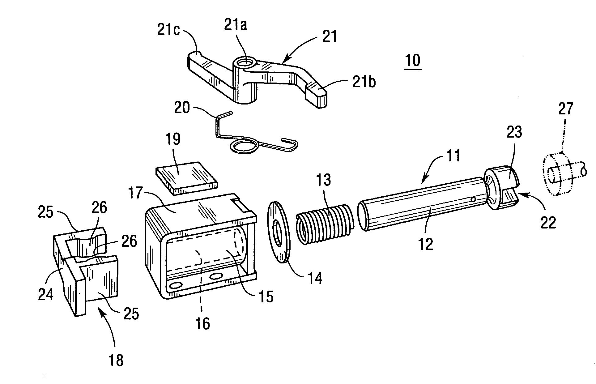
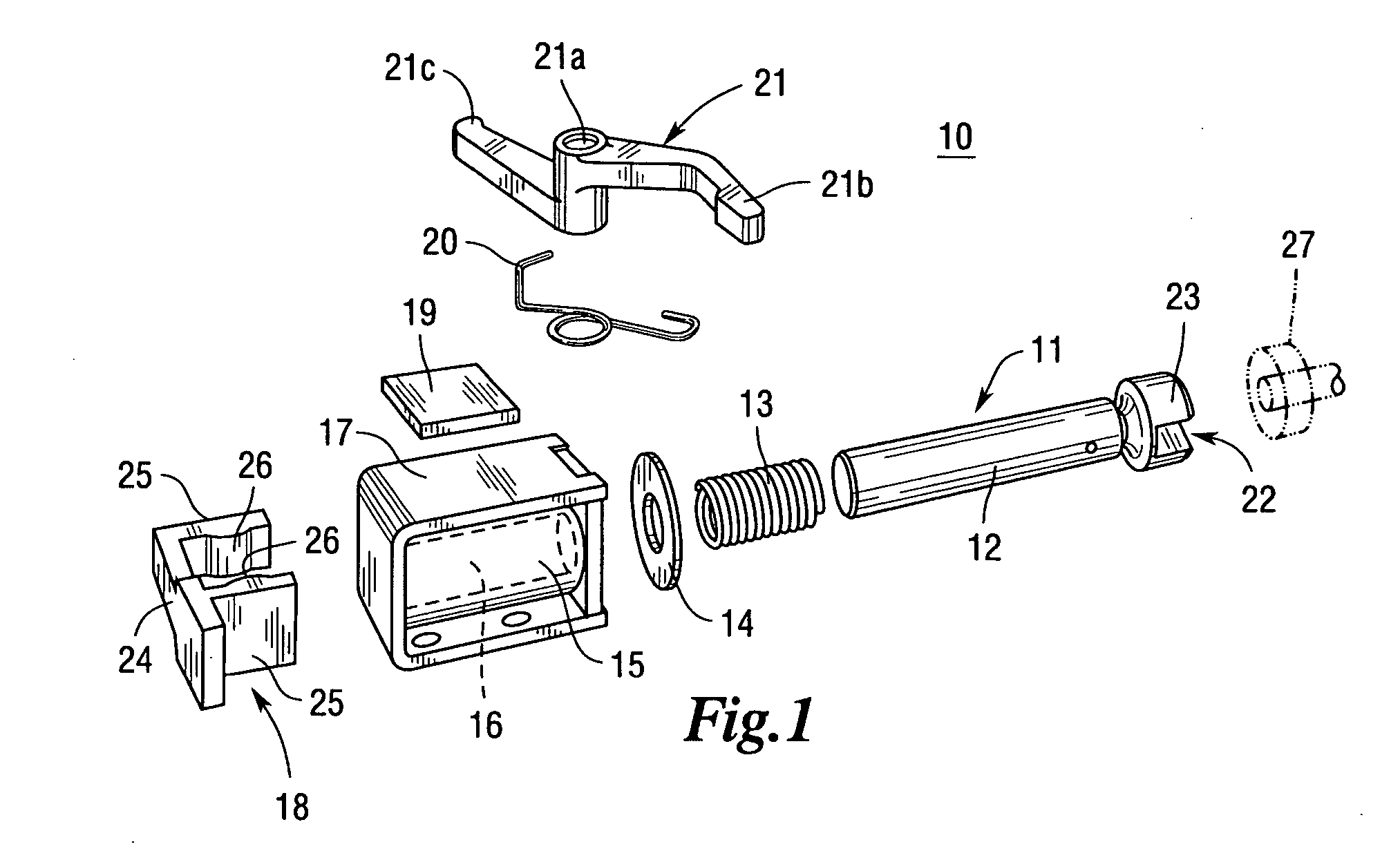
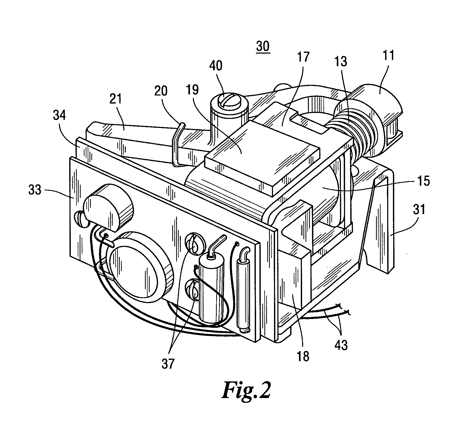
[0019]FIG. 1 shows a tripping device 10 including a coil 15 which is fixedly coupled to a coil frame 17. The coil 15 includes a cylindrical channel 16 (shown in hidden line drawing) which is structured to reciprocatingly receive the first end of a plunger 11. The plunger ...


PUM


Abstract

A tripping device comprises a coil frame, a coil, a plunger, a spring, and an anti-shock device. The coil is fixedly coupled to the coil frame and has a cylindrical channel extending therethrough. The plunger is reciprocatingly received within the cylindrical channel and the spring is structured to bias the plunger within the cylindrical channel. The anti-shock device includes at least one of a number of anti-shock devices structured to eliminate movement of the coil relative to the coil frame and a number of anti-shock devices structured to eliminate movement of the plunger relative to the cylindrical channel. An under-voltage release mechanism comprises a mounting bracket, a tripping device, and an angled support. The mounting bracket includes a first portion and a second portion. The angled support is fixedly coupled to the mounting bracket between the first and second portions and is structured to prevent flexing of the mounting bracket.

Description

BACKGROUND OF THE INVENTION [0001] 1. Field of the Invention [0002] The present invention relates generally to under-voltage release mechanisms and, more particularly, to a shock-resistant under-voltage release mechanism having a shock-resistant tripping device. [0003] 2. Background Information [0004] Numerous types of circuit breakers are known and understood in the relevant art. A circuit breaker is typically configured to interrupt a circuit in response to a trip event (e.g., without limitation, an over-current condition; an under-voltage condition). Generally, circuit breakers include a moveable contact that is placed into electrical contact with a stationary contact to complete an electrical circuit. When desired, a tripping mechanism moves the moveable contact away from the stationary contact to interrupt the electrical circuit. Numerous types of tripping mechanisms are known. [0005] In one type of tripping mechanism, for example, one or more trip buttons are provided which, w...

Claims


Application Information

Patent Timeline
IPC IPC(8): H01H9/00
CPCH01F7/088H01F7/1607H01H3/60H01H50/30H01H71/1054H01H83/12
Inventor SISLEY, JAMES P.HENWOOD, JOHN J.POMAYBO, ROBERT M.
Owner EATON INTELLIGENT POWER LIMITED
Why Eureka
Try Eureka