
Mobile station, communication system, communication control method

a mobile communication system and communication control technology, applied in the field of mobile stations, can solve the problems of reducing the efficiency of radio resource use, affecting the transmission timing of the other mobile stations, and the inability to increase the transmission speed (throughput) of the whole mobile communications system

Inactive Publication Date: 2007-04-12
MITSUBISHI ELECTRIC CORP
View PDF3 Cites 126 Cited by
  • Summary
  • Abstract
  • Description
  • Claims
  • Application Information

AI Technical Summary

Benefits of technology

[0019] In accordance with the present invention, there is provided a mobile station which transmits and receives packet data to and from a base station according to an assigned schedule such as a transmission timing which the above-mentioned base station determines based on priority information about a priority of each packet data received from each mobile station, the mobile station including a transmission data storage unit for temporarily storing a...

Problems solved by technology

A problem with this transmission method is, however, that when a transmission timing and a spreading signal are assigned to a mobile station which is trying to transmit a large amount of packet data to the base station, even if another mobile station which is going to transmit data to be transmitted having a higher priority, such as voice data, as compared with packet data including mail data or the like exists in the system in the meantime, the base station cannot assign any transmission timing and any spreading signal to the other mobile station, and this results in a delay in the transmission timing of the other mobile station and the transmission speed (throughput) of the whole of the mobile communications system cannot be increased, thereby reducing the efficiency of use of radio resources.
Therefore, the base station cannot know the priority of each packet data which each mobile station staying in a service area is trying to transmit thereto in advance.

Method used


Image

  • Mobile station, communication system, communication control method
  • Mobile station, communication system, communication control method
  • Mobile station, communication system, communication control method

Examples


embodiment 1

[0040] The invention according to embodiment 1 will be explained with reference to diagrams.

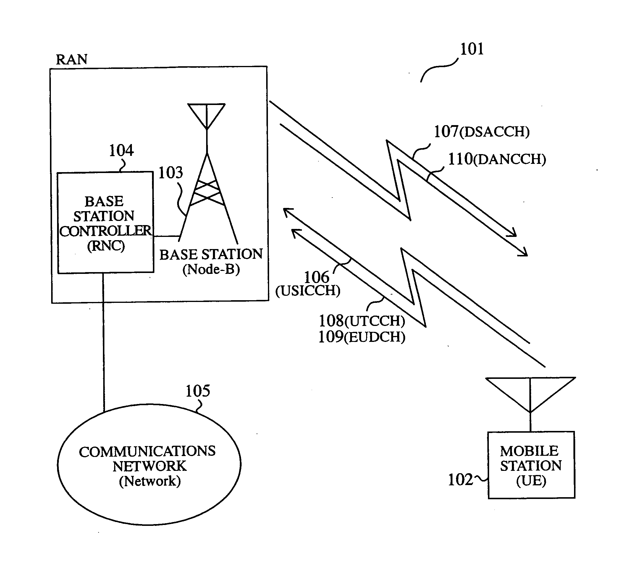
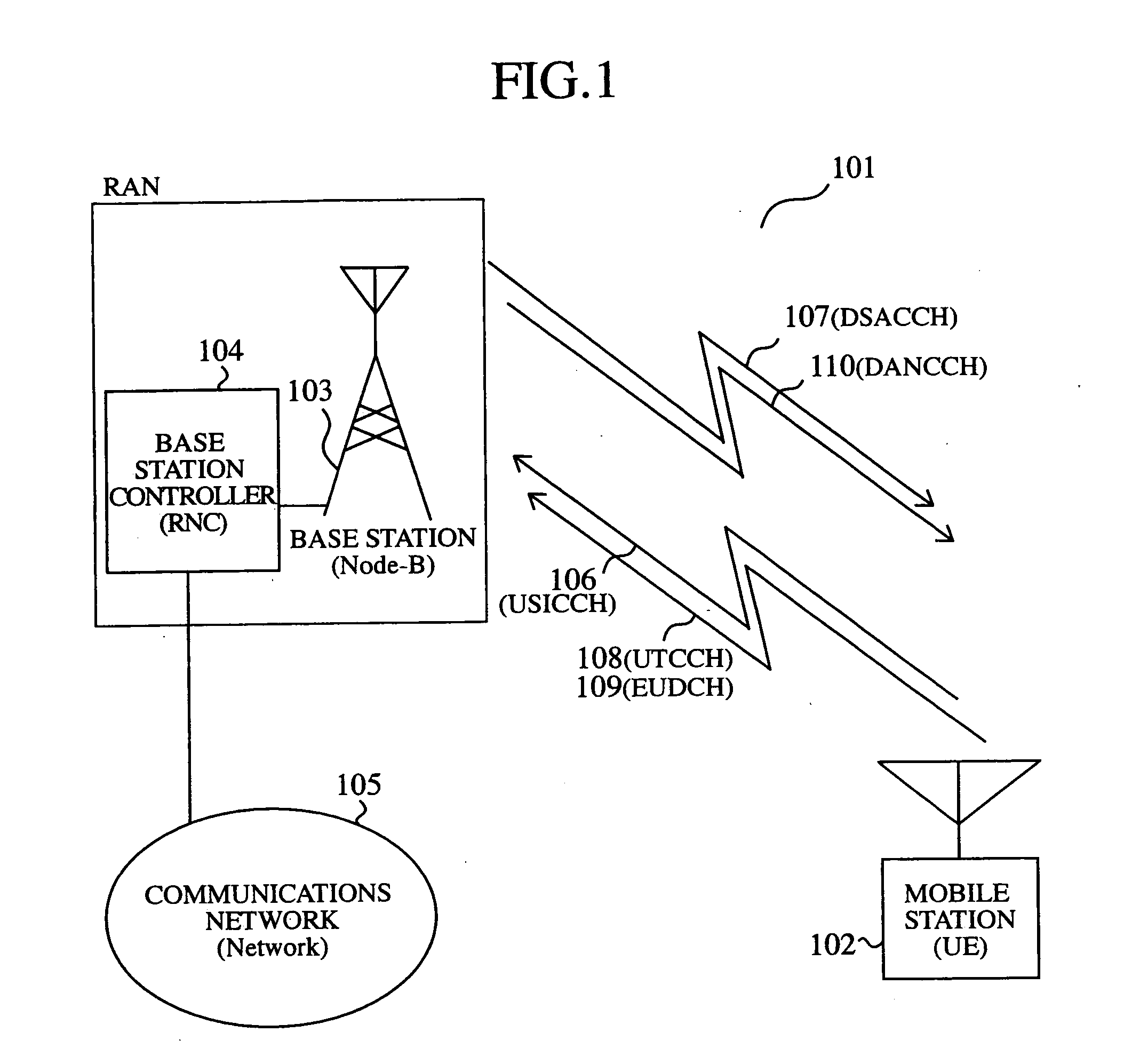
[0041]FIG. 1 is a diagram schematically showing the structure of a communications system in accordance with embodiment 1 of the present invention.

[0042] In FIG. 1, the communication system 101 is provided with a mobile station 102, a base station 103, and a base station controller 104. The base station 103 covers a sector or cell having a certain range, and communicates with two or more mobile stations 102. For the sake of simplicity, only one mobile station 102 is shown in FIG. 1. Communications can be carried out between the mobile station 102 and the base station 103 using two or more channels.

[0043] The base station controller 104 is connected to a network 105, such as a public telephone network, and relays packet communications between the base station 103 and the network 105.

[0044] In W-CDMA, the above-mentioned mobile station 102 is called UE (User Equipment), the base station 103 ...

embodiment 2

[0151] The invention according to embodiment 2 will be explained with reference to the accompanying drawings.

[0152]FIG. 10 is a diagram showing a transmission procedure for transmitting packet data between a mobile station and a base station in accordance with embodiment 2 of the present invention.

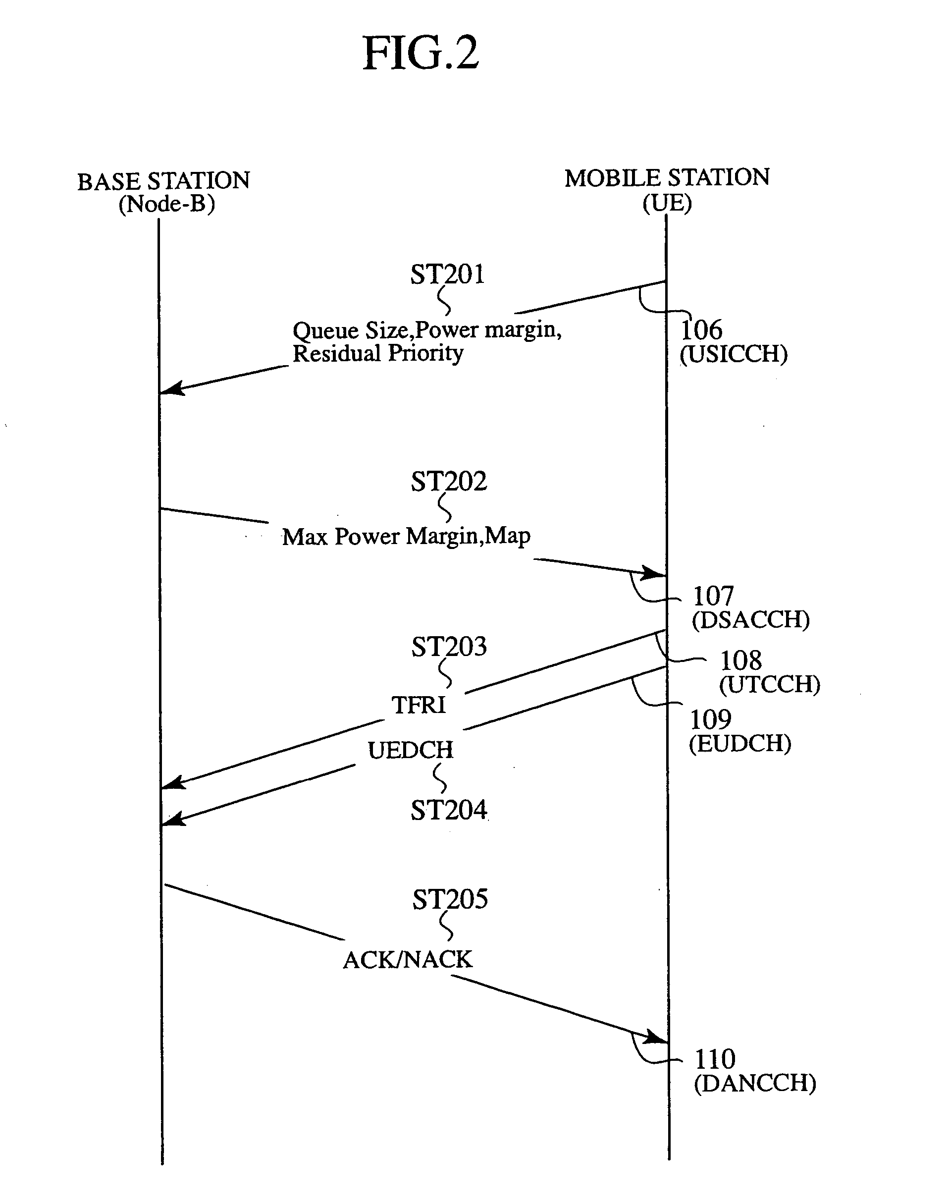
[0153] The transmission procedure shown in FIG. 10 differs from the transmission procedure, as shown in FIG. 2, for transmitting packet data between the mobile station and the base station in accordance with embodiment 1 of the present invention in that the mobile station of this embodiment, in ST1001 and ST1004, sends out residual priority information (Residual Priority) onto a channel (EUDCH) 1009 for data transmission to transmit it to the base station 103, in contrast to the case of FIG. 2 where the mobile station 102 sends out the residual priority information (Residual Priority) onto a channel (USICCH) 106 for transmission request to transmit it to the base station 103.

[0154]FIG. ...

embodiment 3

[0186] The invention according to embodiment 3 will be explained with reference to the accompanying drawings.

[0187] In accordance with embodiment 3, a base station 103 or 1210 uses not only residual priority (Residual Priority) transmitted from a mobile station 102 but also the priority (Priority) of packet data itself, as priority information used for determining a schedule such as a transmission timing at which the base station communicates with each mobile station 102, and switches between them according to an operation mode. Assume that the priority (Priority) of packet data itself is either a priority which a sender written in the header portion of the packet data to be transmitted from the mobile station to the base station desires, which is disclosed in patent reference 2 explained in Background of the Invention, or the type of the packet data, for example.

[0188]FIG. 15 is a sequence diagram of operation mode switching processing for setting of priority information in accor...


PUM


Abstract

A mobile station includes a transmission data storage unit for temporarily storing at least one or more input packet data, a priority control unit for generating priority information which a base station uses for determination of a schedule in advance based on the priority of at least the one or more packet data, and a transmitting unit for transmitting the priority information to the base station. Therefore, to generate a schedule such as a transmission timing at which the base station communicates with each mobile station, the base station can know the priority of packet data stored in each mobile station in advance, and can recognize the existence of a mobile station which is trying to transmit packet data with a high priority to the base station at an early stage. As a result, the base station can assign a transmission timing etc. quickly to the mobile station.

Description

FIELD OF THE INVENTION [0001] The present invention relates to a mobile station which communicates packet data in a mobile communications system with CDMA (Code Division Multiple Access). BACKGROUND OF THE INVENTION [0002] In recent years, a telecommunications protocol which is called a third generation as a high-speed CDMA mobile-communications method is adopted as IMT-2000 in the International Telecommunications Union (ITU), and, as for W-CDMA (FDD: Frequency Division Duplex), commercial services were started in Japan in 2001. The W-CDMA (FDD) method aims at providing a transmission speed of the order, at maximum, of 2 Mbps (Mega bit per sec) for each mobile station, and the first specification of the W-CDMA method was determined, as the released 1999th version summarized in 1999, by the standardization organization 3GPP (3rd. Generation Partnership). [0003] As a document proposed based on this specification, an on-demind channel assignment method for uplink is proposed by R1-0300...

Claims


Application Information

Patent Timeline
IPC IPC(8): H04B7/216H04W72/06
CPCH04W72/0406H04W72/10H04L47/2433H04W28/14H04W72/20H04W72/56H04W72/569H04W72/21H04L47/10
Inventor NIWANO, KAZUHITO
Owner MITSUBISHI ELECTRIC CORP
Features
  • Generate Ideas
  • Intellectual Property
  • Life Sciences
  • Materials
  • Tech Scout
  • Unparalleled Data Quality
  • Higher Quality Content
  • 60% Fewer Hallucinations
Learn More