Micropattern grip surface

Inactive Publication Date: 2007-04-12
GRIP SURFACE TECH
View PDF7 Cites 16 Cited by
  • Summary
  • Abstract
  • Description
  • Claims
  • Application Information

AI Technical Summary

Benefits of technology

[0023] The ridges and grooves provide a multidirectional feel in a golfer's hand under both torque

Problems solved by technology

Some grips have a smooth surface, which is difficult to hold when force is applied to the grip or to the object including the grip, including force applied either around the axis of the grip, that is torsional force, or force applied longitudinally along the axis.
A smooth grip must be held more tightly than a roughened grip, thus compromising the performance of a golf club or like products.
However, particularly when a rubber material grip is sanded, the sealed surface skin of the rubber of t

Method used


Image

  • Micropattern grip surface
  • Micropattern grip surface

Examples


Embodiment Construction

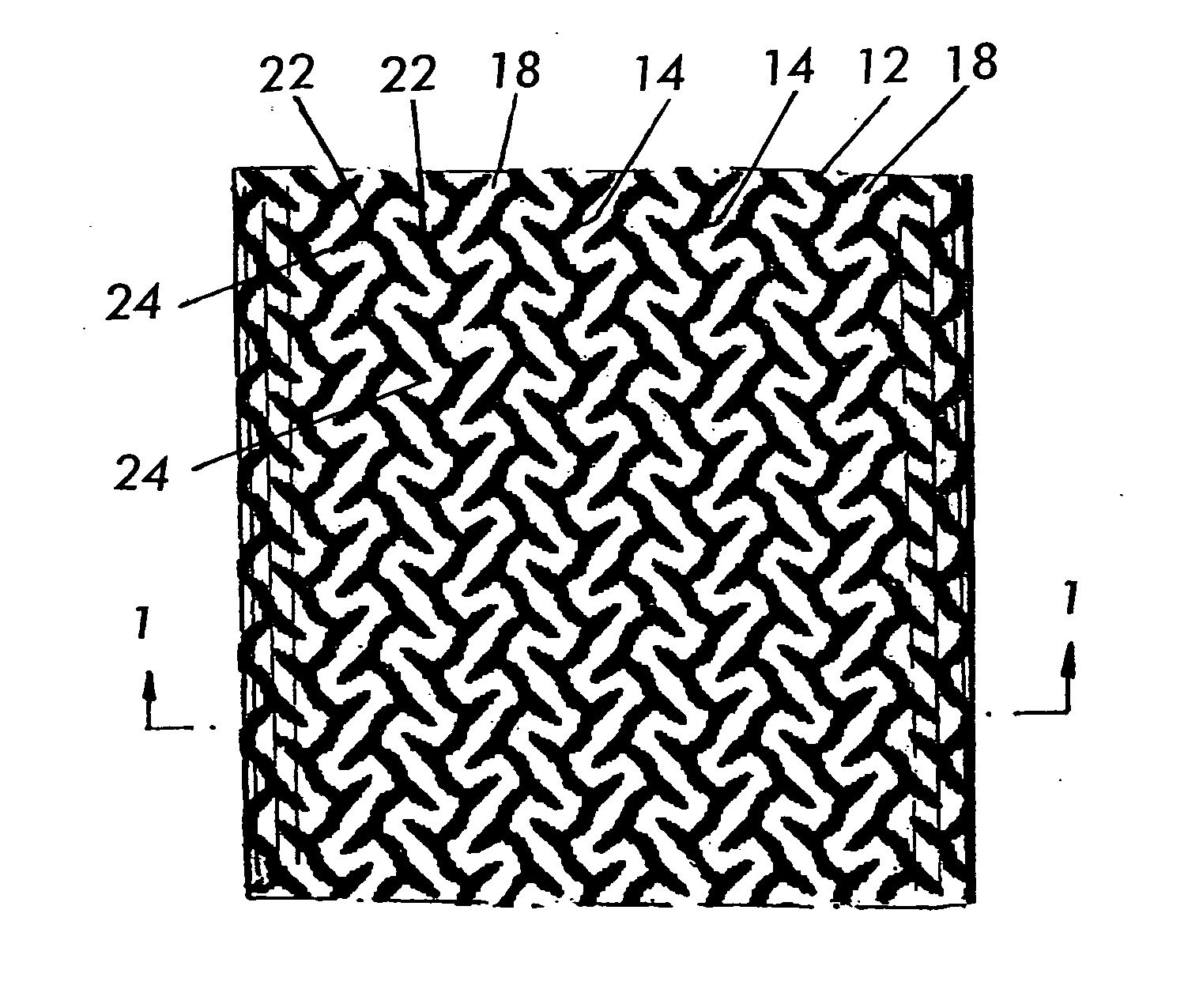
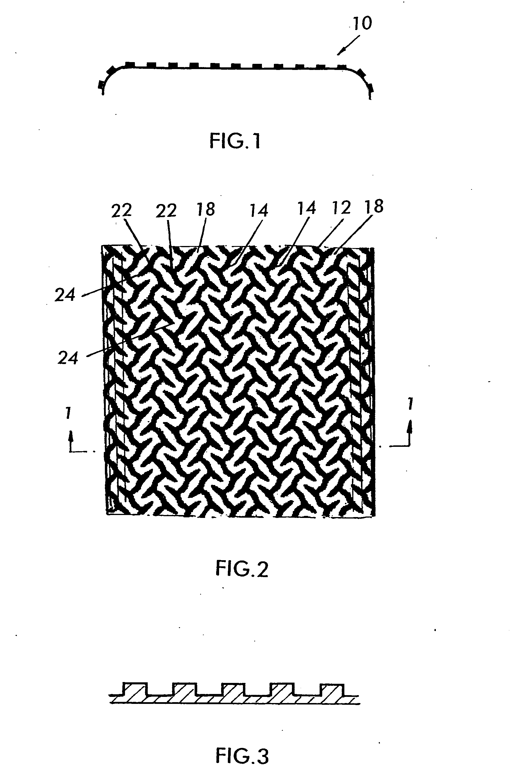
[0027] One preferred embodiment illustrating the present invention concerns a grip surface 10, which carries a micropattern 12 that is seen in plan in FIG. 2 and in section in FIGS. 1 and 3. The particular design of micropattern shown in the drawings is a preferred embodiment, but not the only embodiment of the invention.

[0028] The micropattern 12 is shown considerably enlarged in the drawings to show its features. Being a micropattern with the dimensions described above, the unmagnified pattern is visible to the eye, but its details may not be discerned, and it appears mostly as a texturing of the surface of the grip.

[0029] The micropattern 12, shown enlarged in the drawing, comprises continuous strands 14 or lines of ridges or ribs extending longitudinally along the length or along an axis of the grip, and the ridges are in an array, circumferentially around the longitudinal axis or axes of the grip. Not illustrated are alternative directions of the ridge arrays rather than long...


PUM


Abstract

A micropattern grip surface for use on a grip, and particularly a grip for a golf club, wherein the pattern includes alternating upstanding ridges and grooves between the ridges. In a preferred embodiment, the ridges extend with a generally longitudinal direction of extension component on the grip with a generally circumferential direction of extension component and also may be parallel. The ridges in an embodiment zigzag along the longitudinal direction. In an embodiment, at intersections or bends between the zig and the zag line elements, additional free end barbs extend from the intersections. The density, width and height of the line elements of the ridges are selected to provide drag on the hand or object gripping the grip, preferably in both the longitudinal and circumferential directions, and to give the grip a velvety feel. Alternatively, each of the ridges is comprised of some line elements. Each ridge or a set of line segments thereof may be aligned in a direction of at least one of longitudinally along, circumferentially around, obliquely to the axis or spirally around the grip surface.

Description

CROSS-REFERENCE TO RELATED APPLICATION [0001] This application is based upon and claims benefit of United States Provisional Application No. 60 / 726,074, filed Oct. 12, 2005, to which a claim of priority is hereby made.BACKGROUND OF THE INVENTION [0002] Hand grips on golf clubs and other objects have a circumference which is grasped in a user's hand. Typically, the circumferential surface is at least in part rounded or curved, and may also include flat areas. [0003] Gripping the grip tightly enough should prevent movement of the grip longitudinally along a long axis and / or circumferentially around the axis. The grip surface should be comfortable for the person holding the grip. Further, it would be beneficial for the grip surface to enable removal of moisture, oil, perspiration, etc. from the person's hand when holding the grip, and have a surface which allows the grip to be held with the least amount of hand pressure. [0004] There are various designs of hand grips, of which golf gri...

Claims


Application Information

Patent Timeline
IPC IPC(8): A63B53/14
CPCA63B53/14A63B59/0014A63B60/10A63B60/06A63B60/08A63B60/14
Inventor ROSE, TIMOTHY
Owner GRIP SURFACE TECH
Why Eureka
Try Eureka