Gas turbine engine assembly and methods of assembling same

a technology of gas turbine engines and assembly methods, which is applied in the direction of couplings, marine propulsion, vessel construction, etc., can solve the problems of overall and achieve the effect of increasing the overall weight, design complexity and/or manufacturing costs of such engines

Inactive Publication Date: 2007-04-19
GENERAL ELECTRIC CO
View PDF27 Cites 26 Cited by
  • Summary
  • Abstract
  • Description
  • Claims
  • Application Information

AI Technical Summary

Benefits of technology

[0006] In another embodiment, a spline system for operatively coupling a gearbox to a counter-rotating fan assembly is provided. The spline system includes a first spline assembly coupling an input of said gearbox to a bearing support structure. A second spline assembly slidably couples a first portion of the bearing support structure to a second portion of the bearing support structure. A third spline assembly slidably couples an output of the gearbox to an output structure. The spline system isolates the gearbox from axial loads generated by the counter-rotating fan assembly.

Problems solved by technology

Accordingly, the overall weight, design complexity and / or manufacturing costs of such an engine are increased.

Method used


Image

  • Gas turbine engine assembly and methods of assembling same
  • Gas turbine engine assembly and methods of assembling same
  • Gas turbine engine assembly and methods of assembling same

Examples


Embodiment Construction

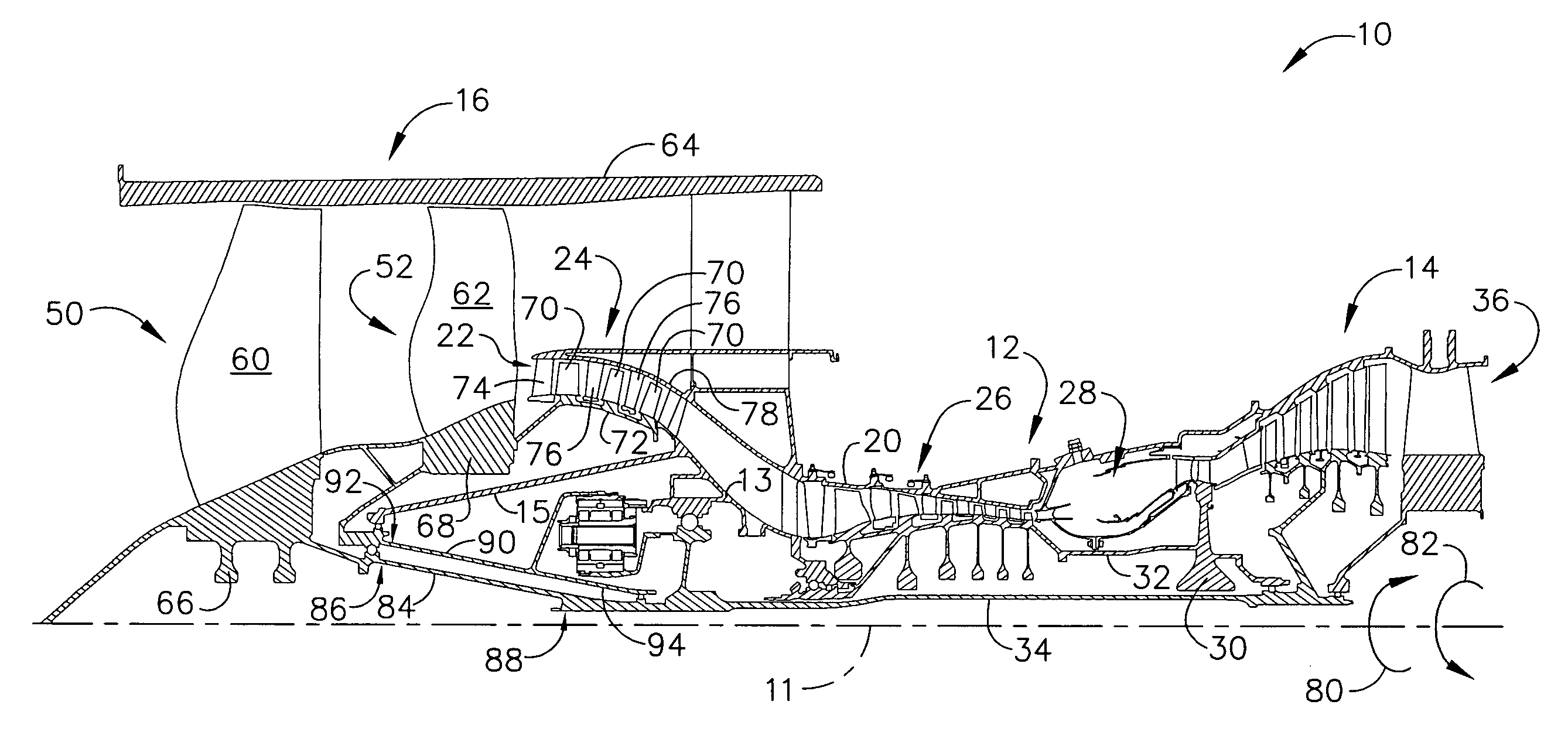
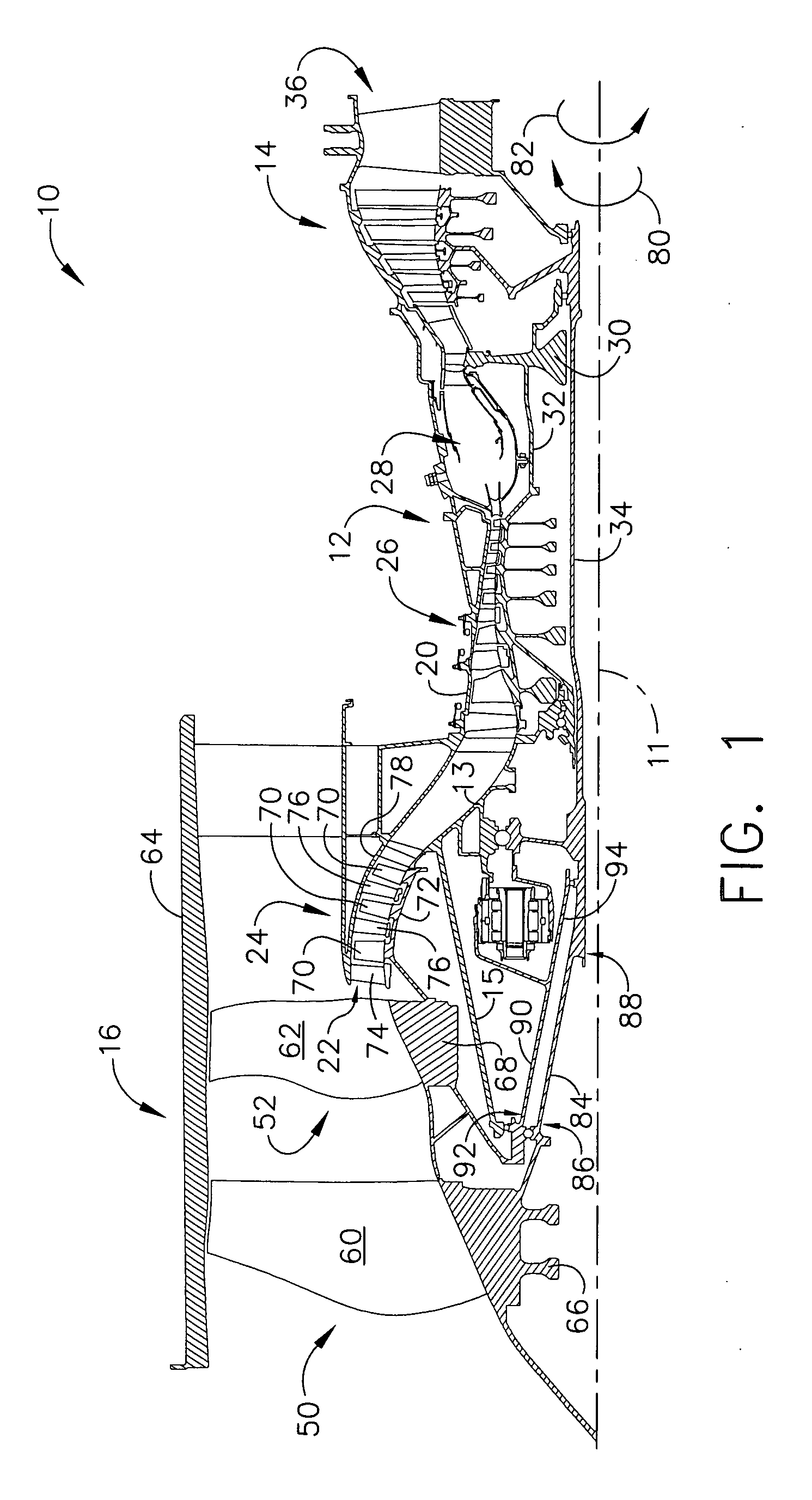
[0012]FIG. 1 is a cross-sectional view of a portion of an exemplary turbine engine assembly 10 having a longitudinal axis 11. In the exemplary embodiment, turbine engine assembly 10 includes a core gas turbine engine 12 generally defined by a frame 13. A low-pressure turbine 14 is coupled axially aft of core gas turbine engine 12 and a counter-rotating fan assembly 16 is coupled axially forward of core gas turbine engine 12.

[0013] Core gas turbine engine 12 includes an outer casing 20 that defines an annular core engine inlet 22. Casing 20 surrounds a low-pressure booster compressor 24 to facilitate increasing the pressure of the incoming air to a first pressure level. In one embodiment, core gas turbine engine 12 is a core CFM56 gas turbine engine available from General Electric Aircraft Engines, Cincinnati, Ohio.

[0014] A high-pressure, multi-stage, axial-flow compressor 26 receives pressurized air from booster compressor 24 and further increases the pressure of the air to a seco...


PUM


Abstract

A method for assembling a gas turbine engine including providing a core gas turbine engine at least partially defined by a frame and having a drive shaft rotatable about a longitudinal axis of the core gas turbine engine. A low-pressure turbine is coupled to a core turbine engine. A counter-rotating fan assembly is coupled to the low-pressure turbine. The counter-rotating fan assembly includes a first fan assembly and a second fan assembly. A booster compressor is coupled to the second fan assembly. A gearbox is securely coupled to the frame so that the gearbox is circumferentially positioned about the drive shaft. The first fan assembly is rotatably coupled to an input of the gearbox such that the first fan assembly rotates in a first direction. The second fan assembly is rotatably coupled to an output of the gearbox such that the second fan assembly rotates in a second direction opposite the first direction.

Description

BACKGROUND OF THE INVENTION [0001] This invention relates generally to gas turbine engines, and more specifically to gas turbine engine assemblies and methods of assembling the same. [0002] At least some known gas turbine engines include a forward fan, a core engine, and a power turbine. The core engine includes at least one compressor, a combustor, a high-pressure turbine and a low-pressure turbine coupled together in a serial flow relationship. More specifically, the compressor and high-pressure turbine are coupled through a shaft to define a high-pressure rotor assembly. Air entering the core engine is mixed with fuel and ignited to form a high energy gas stream. The high energy gas stream flows through the high-pressure turbine to rotatably drive the high-pressure turbine such that the shaft, in turn, rotatably drives the compressor. [0003] The gas stream expands as it flows through the low-pressure turbine positioned forward of the high-pressure turbine. The low-pressure turbin...

Claims


Application Information

Patent Timeline
Patent Type & Authority Applications(United States)
IPC IPC(8): F02K3/04
CPCF02C7/36F02K3/072F05D2250/41F01D25/162F02C3/107F16D1/101F05D2230/642F05D2260/40311F16D2001/103
Inventor MONIZ, THOMAS ORYORLANDO, ROBERT JOSEPH
Owner GENERAL ELECTRIC CO
Why Eureka
Try Eureka