System of attaching an injection system to a turbojet combustion chamber base and method of attachment

a technology of injection system and combustion chamber, which is applied in the direction of machines/engines, mechanical equipment, lighting and heating apparatus, etc., can solve the problem of not being able to enter the combustion chamber, and achieve the effect of eliminating the axial clearan

Active Publication Date: 2007-04-19
SN DETUDE & DE CONSTR DE MOTEURS DAVIATION S N E C M A
View PDF5 Cites 30 Cited by
  • Summary
  • Abstract
  • Description
  • Claims
  • Application Information

AI Technical Summary

Benefits of technology

[0018] Advantageously, the split ring has a coni...

Problems solved by technology

Thus, even if the weld between the chamber base and the deflect...

Method used


Image

  • System of attaching an injection system to a turbojet combustion chamber base and method of attachment
  • System of attaching an injection system to a turbojet combustion chamber base and method of attachment
  • System of attaching an injection system to a turbojet combustion chamber base and method of attachment

Examples


Embodiment Construction

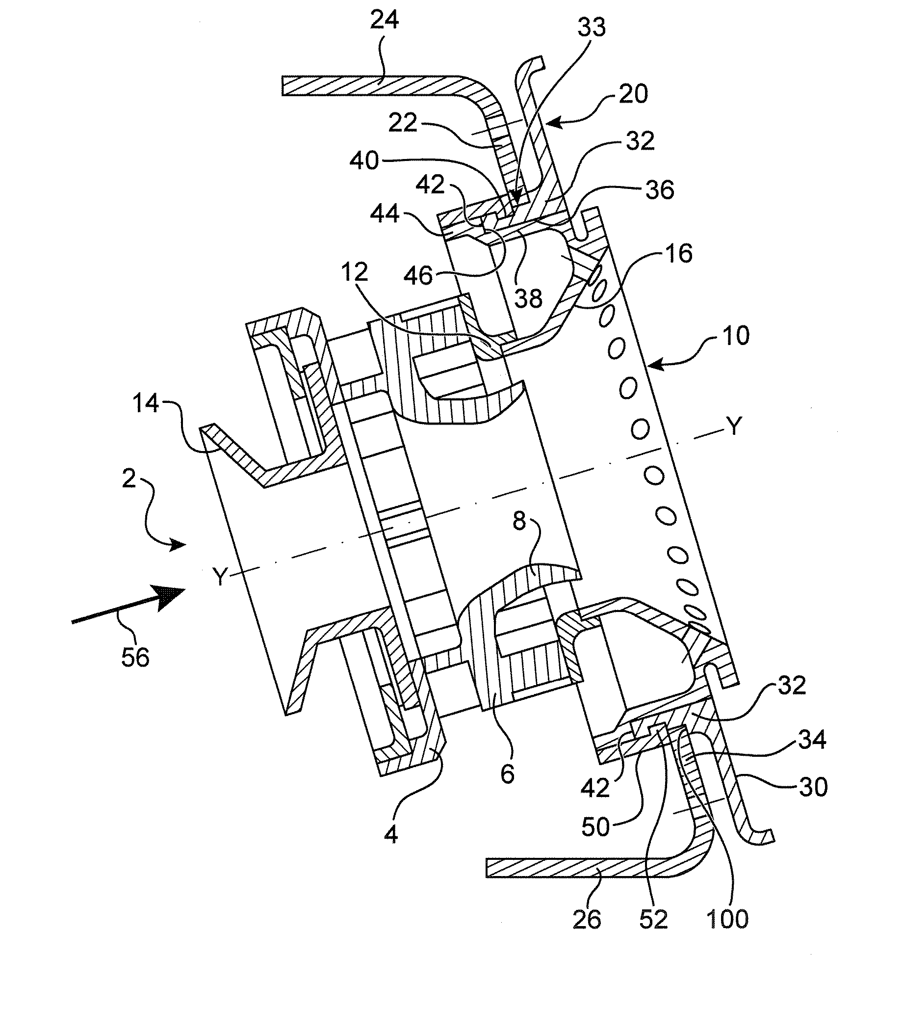
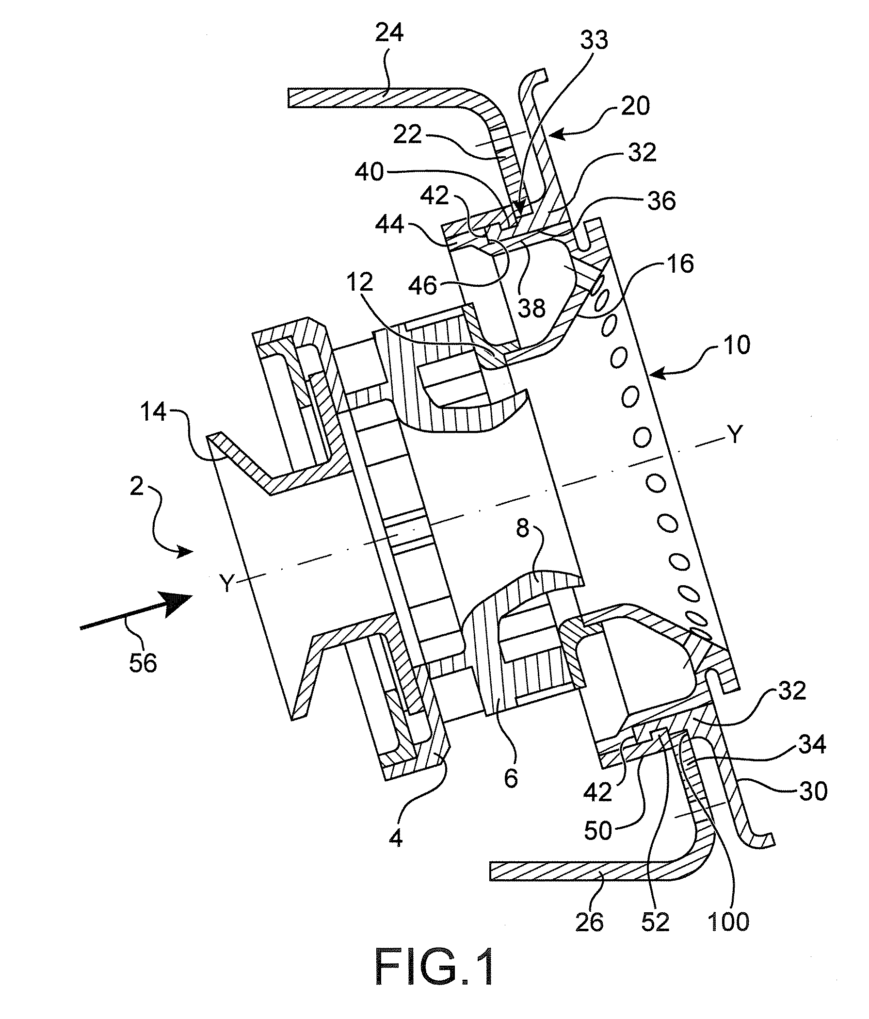
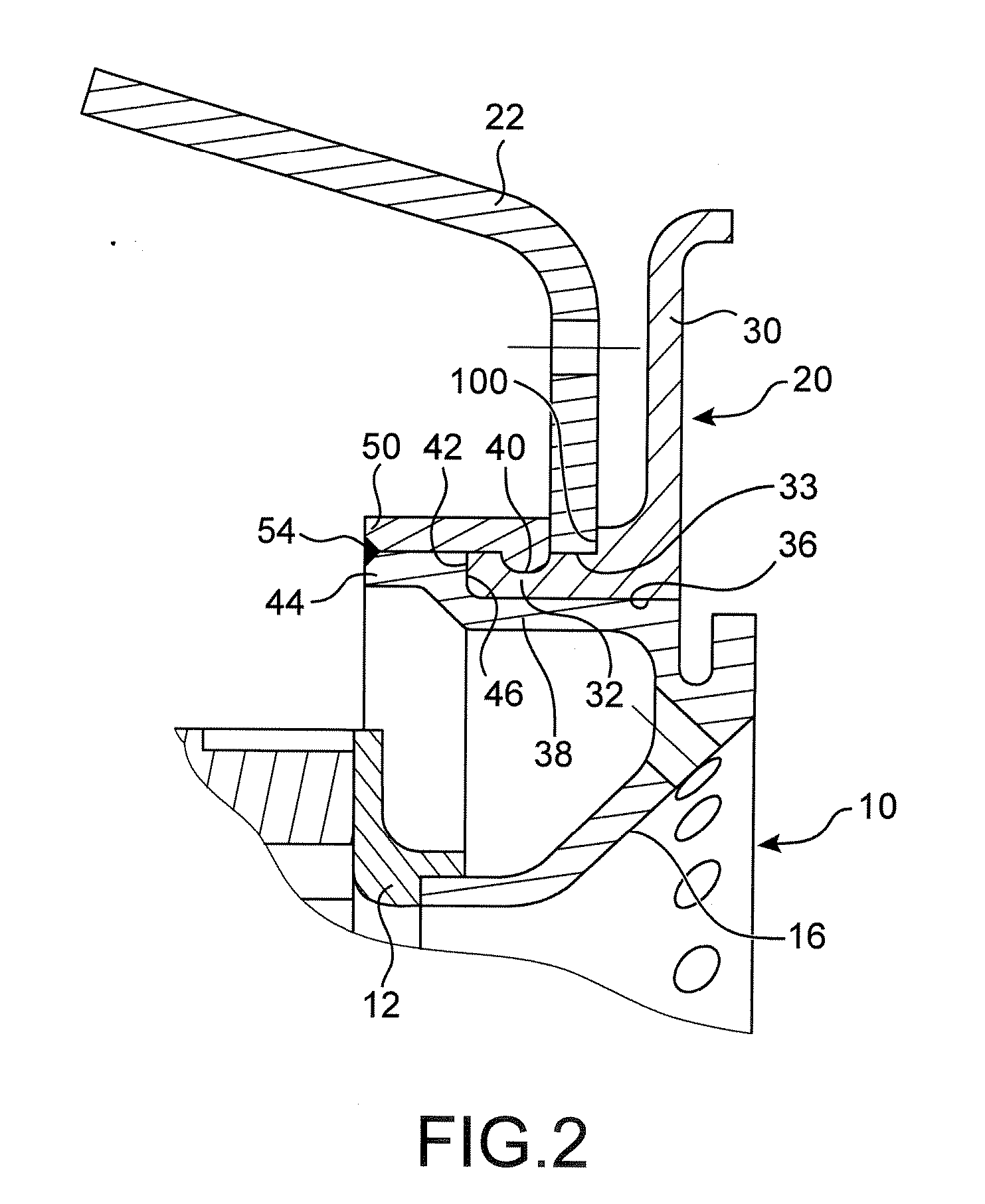
[0040] In FIG. 1, the injection system, indicated in its entirety by the general reference number 2, consists of a fixed portion consisting of a ring 4, a swirler element 6, a venturi 8 and a bowl 10. The swirler element 6 and the bowl 10 are connected to one another via an intermediate ring 12. A sliding crossmember 14 is mounted so as to slide on the ring 4. The swirler element comprises two blade stages whose function is to rotate the air about the longitudinal axis YY of the injection system. The bowl 10 comprises a flared shape 16 whose function is to cause the jet of air and fuel mixture coming out of the venturi 8 to break up.

[0041] A deflector 20 is mounted on the chamber base 22. The chamber base itself comprises two clamping zones 24 and 26. The clamping zone 24 is connected to an outer chamber wall (not shown) and the inner clamping zone 26 is connected to an inner chamber wall, also not shown. A plurality of injection systems, typically from 13 to 32, evenly spaced angu...


PUM


Abstract

A system of attaching an injection system to a turbojet combustion chamber base. It comprises a deflector welded onto the chamber base. The deflector comprises an annular portion having an edge forming a retaining shoulder directed toward the front of the turbojet and the injection system comprises a collar on which is formed a retaining shoulder directed toward the rear of the turbojet and pressing against the retaining shoulder of the deflector.

Description

BACKGROUND OF THE INVENTION [0001] 1. Technical Field [0002] The invention relates to a system of attaching an injection system to a turbojet combustion chamber base. [0003] The combustion chambers of turbojets comprise an inner wall and an outer wall connected at their upstream end via an annular base to define a combustion chamber base. Injection systems evenly distributed over the periphery of the combustion chamber base deliver a mixture of air and fuel that is burned to provide combustion gases. [0004] Each injection system comprises a venturi in which the air and the fuel mix. A bowl, situated downstream of the venturi, has the function of breaking up the jet of air / fuel mixture coming out of the venturi. In addition, a deflector protects the chamber base from the flames of the combustion chamber. [0005] 2. Description of the Prior Art [0006] In a known embodiment (U.S. Pat. No. 4,584,834), the injection system is mounted from downstream, that is to say via the rear of the tur...

Claims


Application Information

Patent Timeline
IPC IPC(8): F23R3/14F23R3/60
CPCF23R3/10F23R3/283F23R3/60
Inventor HERNANDEZ, DIDIER HIPPOLYTELUNEL, ROMAIN NICOLASPIEUSSERGUES, CHRISTOPHEPINCHON, DAVIDSEVI, GUILLAUME
Owner SN DETUDE & DE CONSTR DE MOTEURS DAVIATION S N E C M A
Why Eureka
Try Eureka