

Lift device of a blind
a technology of lifting device and blind cloth, which is applied in the direction of door/window protective device, screen, construction, etc., can solve the problems of difficult to lift blind cloth, people in a room are afraid of being seen through windows, etc., and achieve the effect of rotational velocity ratio
- Summary
- Abstract
- Description
- Claims
- Application Information
AI Technical Summary
Benefits of technology
Problems solved by technology
Method used
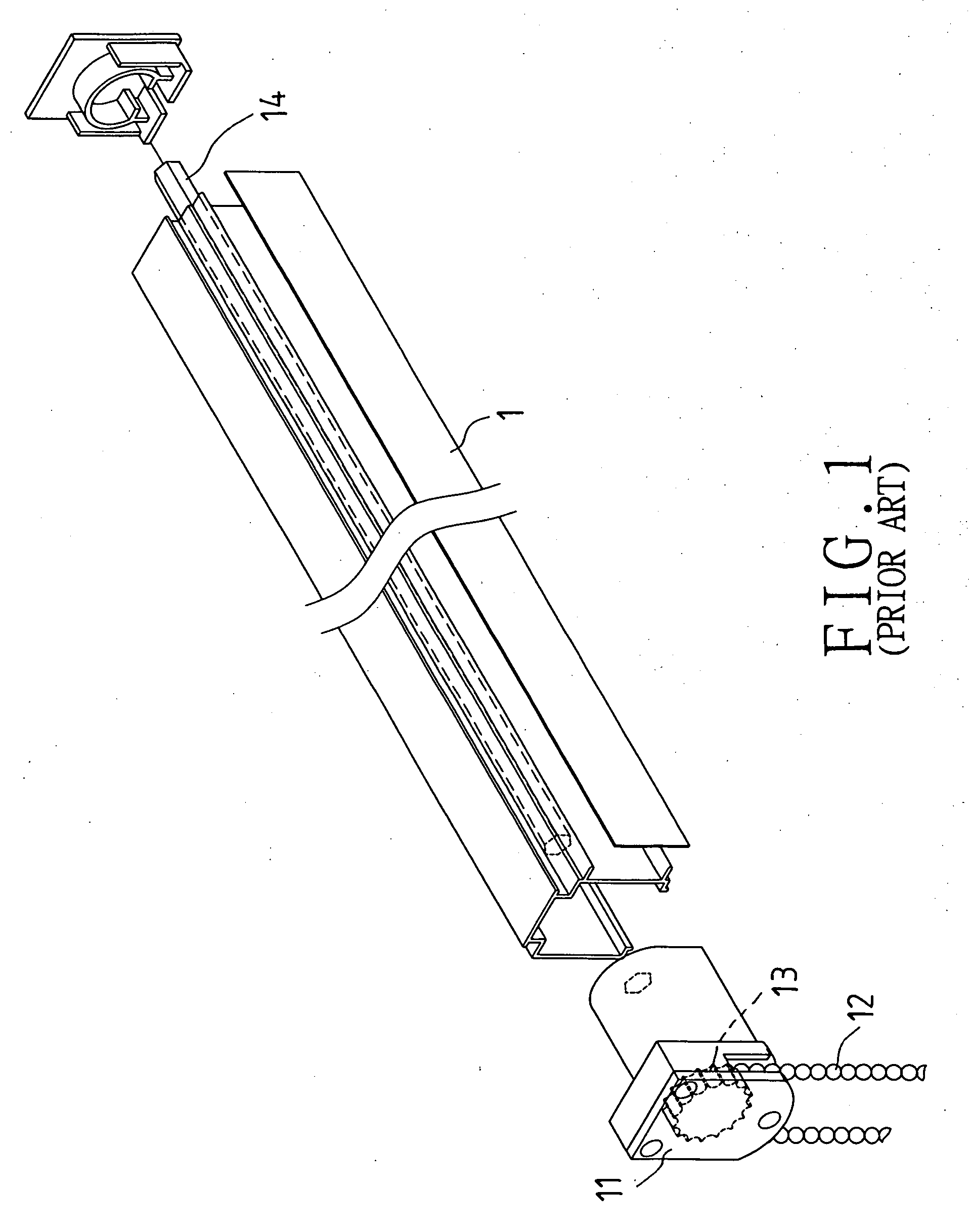
Image

Examples
Embodiment Construction
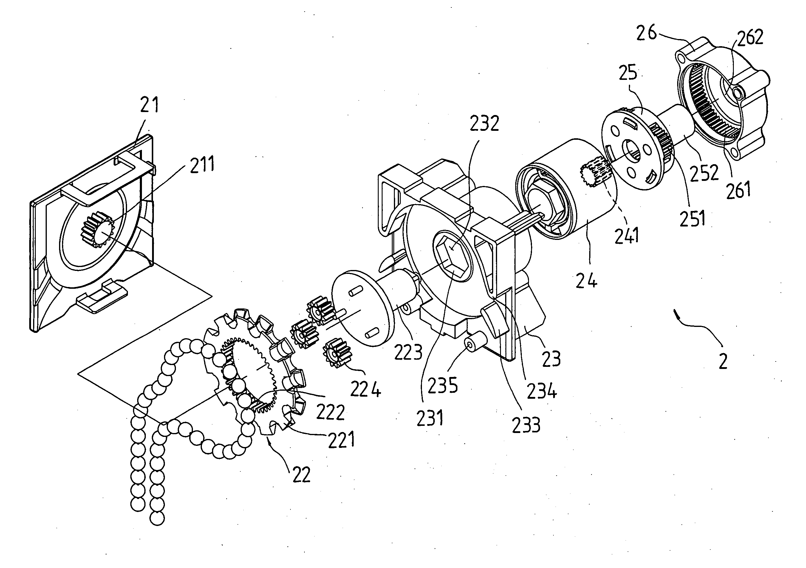
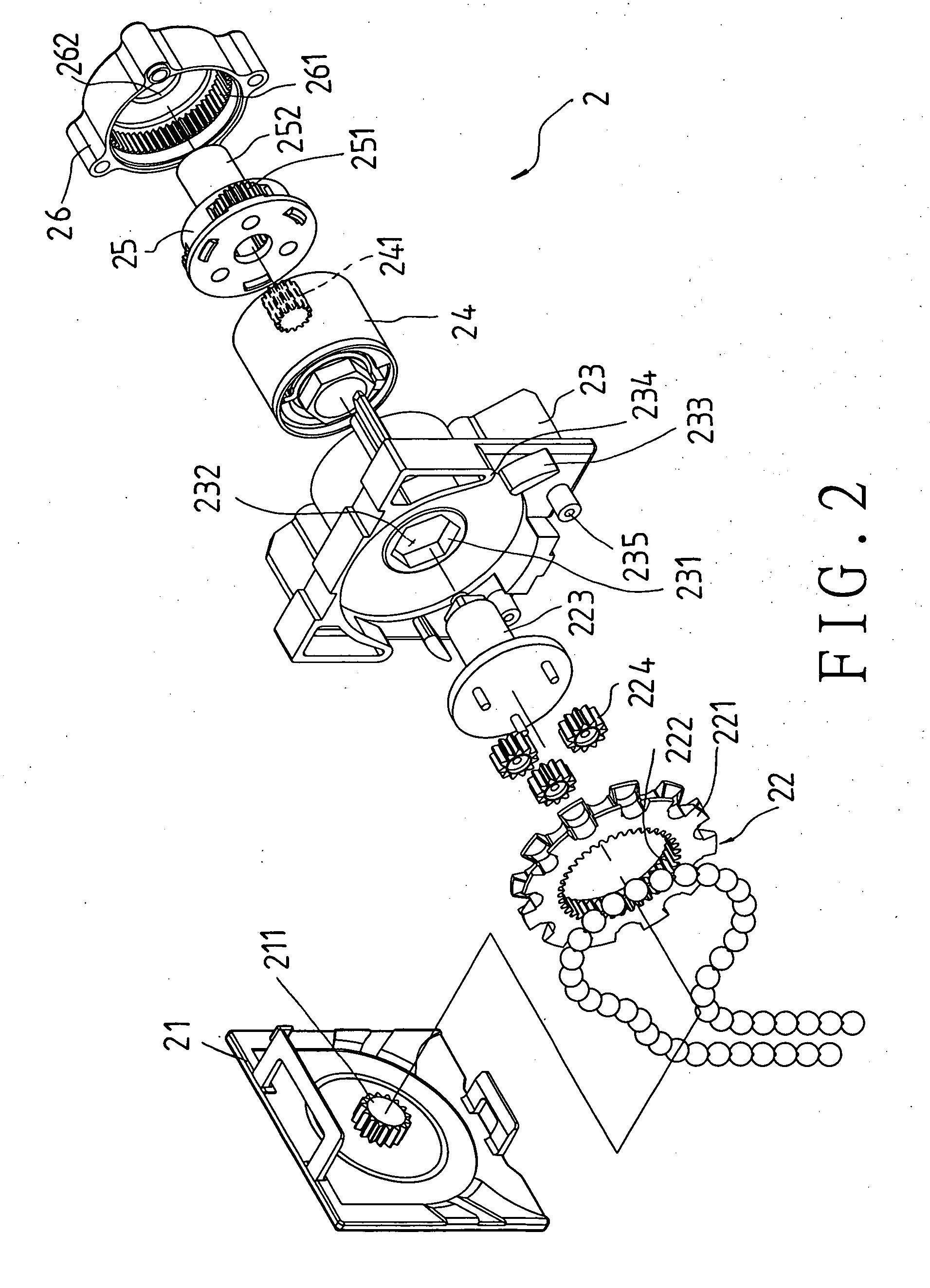
[0016] Referring to FIGS. 2 and 3, a preferred embodiment 2 of a lift device of a blind in the present invention includes:
[0017] a fixed support 21; the fixed support 21 is securely joined to a tail end of an elongate main support member of a blind; the fixed support 21 has a gear 211 on an inner side thereof;
[0018] a rotating member 22 positioned next to the inner side of the fixed support 21; the rotating member 22 includes a rotating disk 221, a rotating shaft 223, and several planetary gears 224; the rotating disk 221 is next to the fixed support 21, and it has an internal gear 222; the rotating shaft 223 is connected to the planetary gears 224 while the planetary gears 224 are engaged with the internal gear 222 as well as the gear 211 of the fixed support 21 such that a planetary gear train is formed;
[0019] a pulling member passed over the rotating member 22; the pulling member can be a bead chain or a cord;
[0020] a connecting and supporting member 23 securely joined to the...
PUM
 Abstract
Description
Claims
Application Information