Method and apparatus for sensing and controlling residual mass on customer images

a residual mass and image technology, applied in electrographic process apparatus, instruments, optics, etc., can solve the problems of limited information provided by measuring residual mass with a point sensor like an etac, limited information provided by typical etac sensors, and limited transfer performance, etc., to achieve the effect of improving print quality performance and stability

a residual mass and image technology, applied in electrographic process apparatus, instruments, optics, etc., can solve the problems of limited information provided by measuring residual mass with a point sensor like an etac, limited information provided by typical etac sensors, and limited transfer performance, etc., to achieve the effect of improving print quality performance and stability

US20070086799A1Active Publication Date: 2007-04-19XEROX CORP

Image

  • Method and apparatus for sensing and controlling residual mass on customer images
  • Method and apparatus for sensing and controlling residual mass on customer images
  • Method and apparatus for sensing and controlling residual mass on customer images

Examples


Embodiment Construction

[0018] For a general understanding of the features of the disclosed system and method, reference is made to the drawings, which are for purposes of illustration and are not representative of size or scale. In the drawings, like reference numerals have been used throughout to identify identical elements.

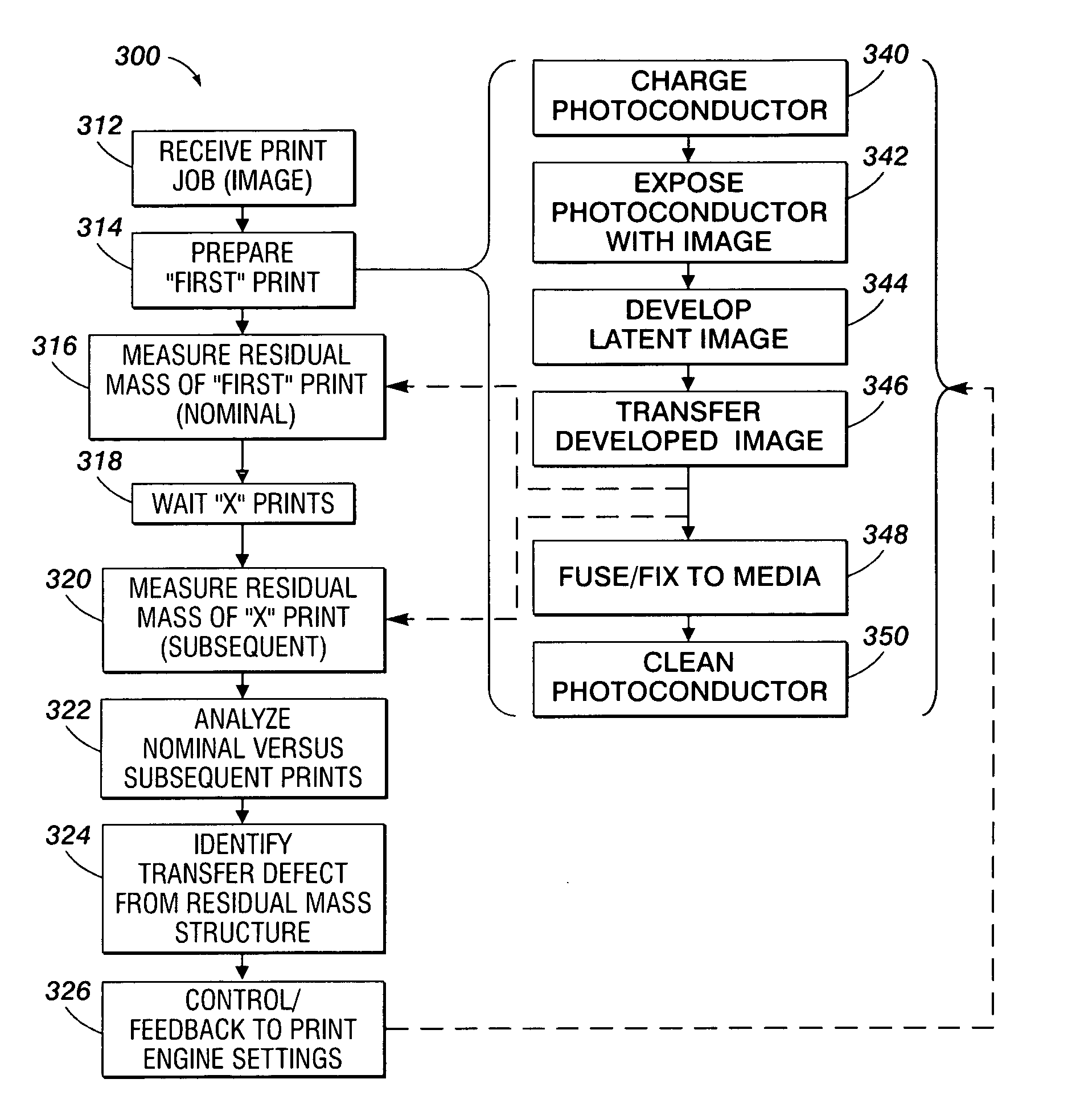
[0019] When examining transfer performance by sensing the residual mass on a photoreceptor, prior methods utilized residual mass sensing and a suitable closed- loop control system to optimize transfer efficiency (or average residual mass levels) in the xerographic system. Because of the inability to discern between various types of transfer related defects, these prior methods were not completely effective at controlling the output of the transfer process. For example, to correct a problem with transfer induced point deletions, the transfer field would typically be reduced. However, to correct a problem with transfer induced mottle, the transfer field would typically be increased. As...


PUM


Abstract

Disclosed is a method and apparatus for sensing residual toner mass after transfer of a xerographic image, to facilitate the identification and characterization of different types of transfer defects. The technique employed utilizes a nominal residual mass signature, measured at the start of a job, in conjunction with subsequent residual mass signature, where the calculated difference between the nominal and subsequent signatures is used to indicate transfer defects and changes in transfer efficiency.

Description

CROSS-REFERENCE TO RELATED APPLICATIONS [0001] U.S. patent application Ser. No. 11 / 094,454, for a FULL-WIDTH ARRAY SENSING OF TWO-DIMENSIONAL RESIDUAL MASS STRUCTURE TO ENABLE MITIGATION OF SPECIFIC DEFECTS, filed Mar. 31, 2005 by Aaron M. Burry et al. is hereby incorporated by reference in its entirety. [0002] A method and apparatus is disclosed for sensing residual mass after transfer of a xerographic image, to facilitate the identification and characterization of different types of transfer defects. The technique employed utilizes a nominal residual mass per unit area (RMA) measured at the start of a job in conjunction with subsequent residual mass per unit area measurements, where the calculated difference between the nominal and follow-up residual mass per unit area is used to indicate transfer defects—such as a loss of transfer efficiency in a particular region of a document. BACKGROUND AND SUMMARY [0003] As disclosed in U.S. Pat. No. 5,887,221 to Grace; and U.S. Pat. No. 5,54...

Claims


Application Information

Patent Timeline
19 Apr 2007
Publication
US20070086799A1
IPC
G03G15/00
CPC
G03G15/1645; G03G2215/00042; G03G2215/1609; G03G15/5041
Inventors
BURRY, AARON M.; FLETCHER, GERALD M.