Invisible spring aligner

a technology of aligners and springs, applied in the field of orthodontic appliances, to achieve the effect of enhancing retention of appliances, strong and stable customized reference, and improving esthetics

Inactive Publication Date: 2007-04-19
GREAT LAKES ORTHODONTICS
View PDF4 Cites 118 Cited by
  • Summary
  • Abstract
  • Description
  • Claims
  • Application Information

AI Technical Summary

Benefits of technology

[0006] It would, therefore, be highly desirable to provide a spring aligner orthodontic appliance having all the functional capabilities of the appliance of U.S. Pat. No. 6,435,871 with the added benefit of an invisible cosmetic advantage. The appliance of this invention includes a clear plastic component which has a posterior portion that extends over the labial surfaces of the teeth to provide a sufficiently strong and stable customized reference against which the teeth can be aligned, clarity for improved esthetics, enhanced retention of the appliance, and reduced need for retention adjustments. The anterior portion of the clear plastic component may comprise an elastic orthodontic chain, silicone, or other suitable clear material.

Problems solved by technology

This preprogrammed appliance makes adjustments virtually unnecessary.

Method used


Image

  • Invisible spring aligner
  • Invisible spring aligner
  • Invisible spring aligner

Examples


Embodiment Construction

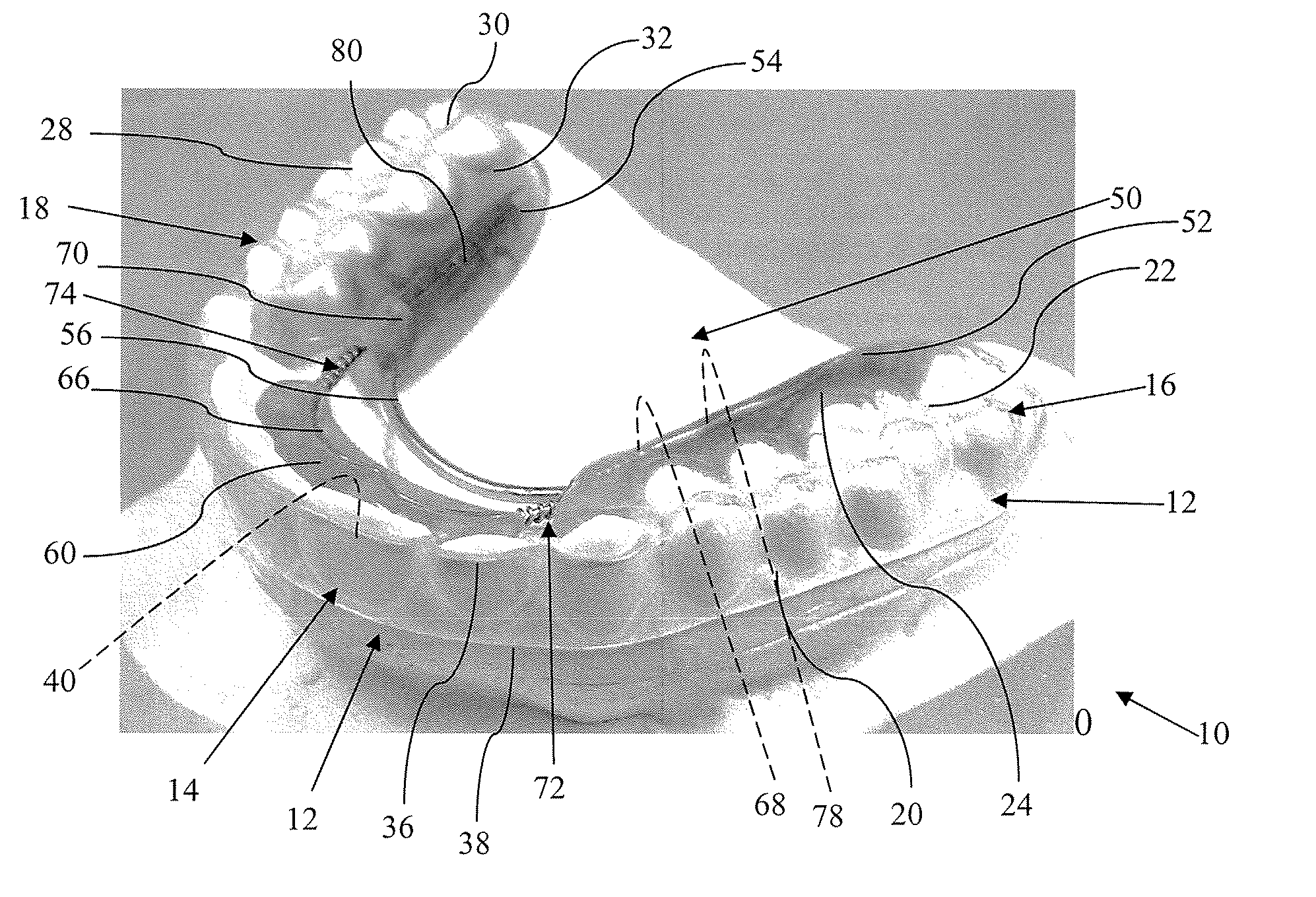
[0027] Referring to FIG. 1, the appliance 10 of the invention includes a clear plastic labial component generally designated 12 which extends over the labial surfaces of the teeth and which has an anterior portion 14 and a pair of posterior portions 16 and 18, the posterior portions being on opposite sides of the dental arch. In the embodiment shown in FIG. 1, the anterior portion 14 and posterior portions 16, 18 comprise an integral or continuous plastic body. In accordance with this invention, anterior portion 14 and posterior portions 16, 18 are in direct contact with the labial / exterior surfaces of the teeth so that only those surfaces of the teeth are visible through the clear, substantially transparent plastic component 12 of the appliance. There is nothing between the labial / exterior surfaces of the teeth and the body of component 12. In other words, other than the clear plastic labial component 12 there are no other components of the appliance externally visible to an observ...


PUM


Abstract

An orthodontic appliance for positioning one or more anterior teeth in a jaw of a patient comprising a clear labial component which extends over the labial surfaces of the patient's teeth and which has an anterior portion and a pair of posterior portions on opposite sides of the dental arch. The anterior and posterior portions of the labial component are in direct contact with the exterior surfaces of the teeth so that no other components of the appliance are located between the anterior and posterior portions of the labial component and those exterior surfaces of the teeth. A lingual component is located within the patient's dental arch for supporting the appliance and for applying force to the patient's anterior teeth, the lingual component operating to move the anterior teeth against the anterior portion of the labial component which serves as a reference against which the teeth are positioned.

Description

CROSS REFERENCE TO A RELATED APPLICATION [0001] Applicants claim priority based on U.S. Provisional Patent Application No. 60 / 700,671 filed Jul. 20, 2005 entitled “Invisible Spring Aligner” which is incorporated by reference.BACKGROUND OF THE INVENTION [0002] This invention relates generally to orthodontic appliances, and more particularly to appliances for correction of problems specific to the anterior teeth. [0003] Many variations of maxillary and mandibular removable tooth moving appliances exist. Some are referred to as orthodontic spring retainers, e.g. 3×3 Spring-Clip, Modified Design, Super Spring and Inman Aligner. Most of these designs are limited in the amount of tooth-movement that can be obtained from a single appliance. They also have cosmetic limitations, in that they have metal components on the facial surfaces of the teeth. [0004] Removable, orthodontic retainer-like appliances typically contain wire clasps and frameworks for tooth alignment, which are placed along ...

Claims


Application Information

Patent Timeline
Patent Type & Authority Applications(United States)
IPC IPC(8): A61C3/00
CPCA61C7/12
Inventor WILLISON, BRIAN D.INMAN, DONAL P.
Owner GREAT LAKES ORTHODONTICS
Why Eureka
Try Eureka