Triangular red LED warning device

a warning device and triangular technology, applied in the direction of identification means, instruments, ways, etc., can solve the problems of difficult detection or inspection of the accident car, inability to make various led signals, and device is impossible to dispatch any other type of luminous signals, etc., to achieve waterproof

Inactive Publication Date: 2007-04-26
HORIBATA HIROSHI
View PDF6 Cites 11 Cited by
  • Summary
  • Abstract
  • Description
  • Claims
  • Application Information

AI Technical Summary

Benefits of technology

[0017] The switching circuit of the flashing board comprises multiple transistors, resistances and condensers to regulate a flash interval of the red LED per minute and may be connected in series with only one of the three sets of the LED circuit, for simple assembly and low cost of the board, however, the switching circuit may also be connected to each LED set respectively to make a flashing flow of the each LED set or each LED bulb by regulating in order a transistor switching interval per one LED set or one LED bulb, as usual.
[0018] An embodiment of the present invention provides a triangular red LED warning device, which can be received conveniently in a suitable box and provided always at a narrow space of the passenger car, a small truck, etc., such as a trunk or a box under a driver or passenger seat.
[0020] An embodiment of the present invention provides a triangular red LED warning device, which can form easily various luminous or flashing signals such as character signals, geometrical signals, traffic signals, etc., to awaken attention of the traffics or the passengers to prevent an accident at night.
[0021] An embodiment of the present invention provides a triangular Red LED warning device, which can be waterproofed easily with a thin plastic cover.
[0022] An embodiment of the present invention provides a triangular red LED warning device, which provides an economical switching circuit to reduce electrical and manufacturing cost.
[0023] An embodiment of the present invention provides a triangular red LED warning device, which can make a flashing light flow from one of the red LED flashing board to the others, in order, repeatedly.

Problems solved by technology

However, discernment or check of the accident car was actually very difficult under bad weather conditions such as rainy weather and thick fog, and even when the weather condition is very fine, a same danger which may lead a secondary accident, is in the powerful headlight of an oncoming car, because the red reflective light from the warning board at the accident spot is negated.
It is needless to say that the triangular red warning device in this embodiment, can be easily composed on or decomposed into the receiving box because the device and box are made in a body, however, it seems to be impossible to make various different LED signals from those signal boards by fixing frictionally one luminous side board on its other side board at each connection between the three side boards of the device, without using of a special setting screw or a frictional holding means, even if the board may form an other character signal temporally.
The device is impossible to dispatch any other type of luminous signals except for the triangular signal, accordingly.
The folding or setting up operation for the triangular red LED device are just same as a well known triangular warning plate or board, and is very simple to do it, however, it is somewhat inconveniently because the tightening means attached in a common through hole of the both ends of the base side board, for fixing the both oblique side boards to the former, has to be controlled every time, by a tightening means such as a screw bolt with the thumb and an index figure to fix the both at desired degree within 180 degrees, and consequently its firm tightening for setting up the later at desired angle to the former, is very difficult, and the set up former was frequently fallen down by gravity itself and the electric connections in the device were some time broken down.

Method used


Image

  • Triangular red LED warning device
  • Triangular red LED warning device
  • Triangular red LED warning device

Examples


Embodiment Construction

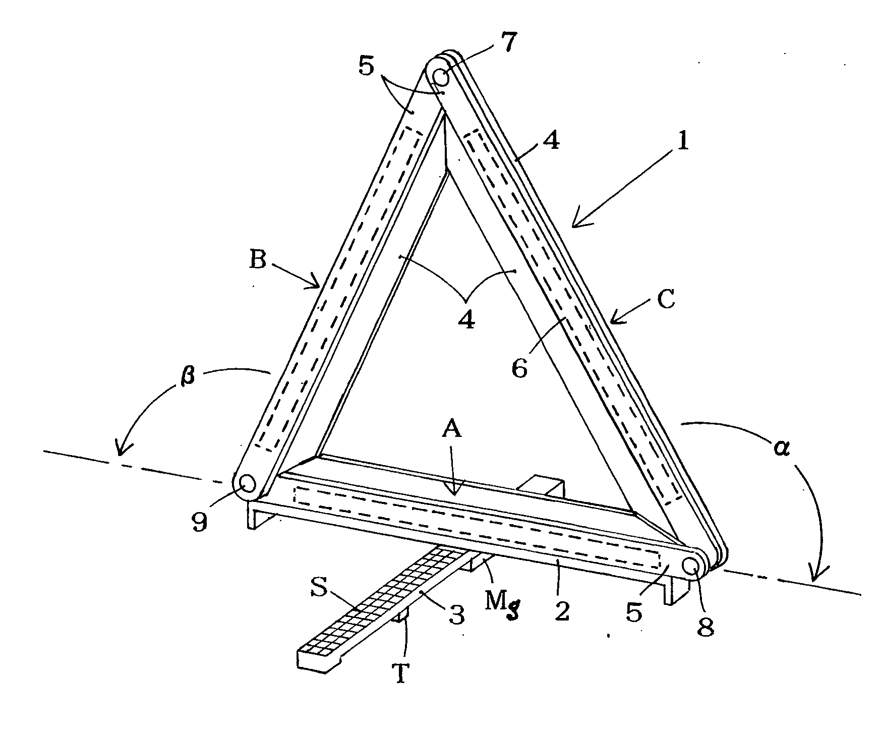
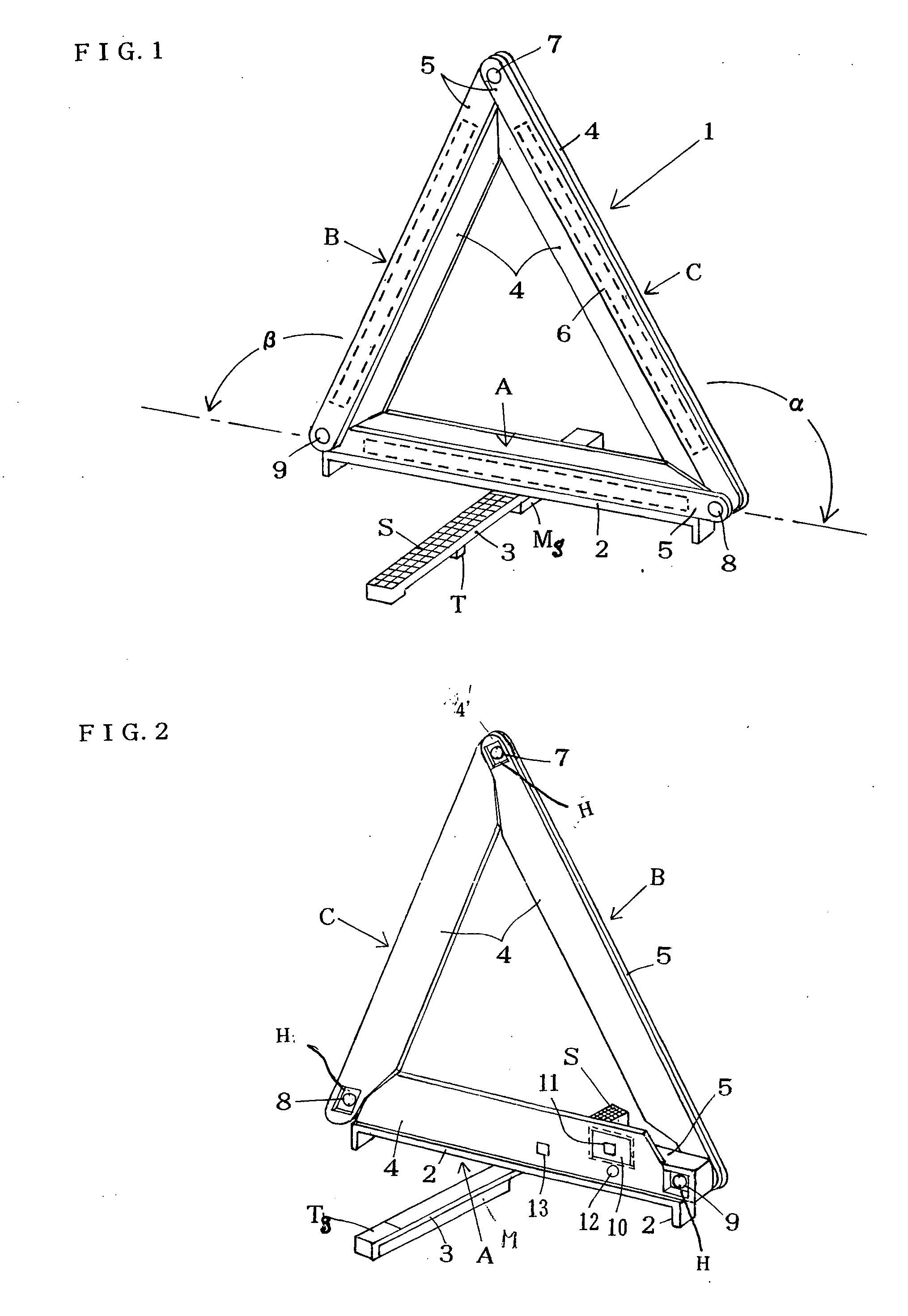
[0036] Referring now to drawings and particularly FIGS. 1 and 2, a triangular red LED flashing board warning device 1 comprises a base side red LED flashing board A fixed on a pair of supporting plates 2, 3 providing two legs at its both and two oblique side red LED flashing boards, and can be changed freely into various flashing signals.

[0037] The each oblique side board B and C comprises a plastic base plate 4 providing a fin 4′ for reinforcement of reflected red LED light and a rectangular hollow portion receiving a red LED circuit board 6 respectively, and a red refractive cover 5, and the both are connected detachably by the connecting means 7 as described hereunder, at neighborhood of their apex.

[0038] The base side board A comprises a plastic base plate 4 and a red reflective over 5, as same as the oblique side board B, C, but it is made rather thicker than the oblique side board, due to receiving the red LED circuit board 6, and an electric power source 11 and so on.

[0039...


PUM


Abstract

A triangular red LED warning device comprises a compact box. A pair of oblique side red LED flashing boards, a base side red LED flashing board and a pair of supporting leg plates. The pair of oblique side red LED flashing boards are connected frictionally by a frictional tightening means at it's each one end to both ends of the base side red LED flashing board, and their each other ends are also connected detachably by means of an elastic connecting pin at neighborhood of the vertical angle, which is formed by the both oblique side boards. Thus, the triangular red LED flashing board can make various signal forms by frictional rotation and stoppage of the each oblique side board for a suitable degree against gravity, and can be freely folded to be received into a compact box after using.

Description

CROSS-REFERENCE TO RELATED APPLICATIONS [0001] This application claims the benefit of a priority under 35 USC 119(a)-(d) to Japanese Utility Model Application No. 2005-9691 filed Oct. 20, 2005 the entire contents of which are hereby incorporated by reference. FIELD OF THE INVENTION [0002] This invention relates to a traffic warning light especially a triangular red LED warning device which can change its signal form and can be used conveniently for the warning equipment for traffic control, traffic accident, or road repair. BACKGROUND OF THE INVENTION [0003] Customary, the passenger cars, private cars, etc., are imposed legally a duty to carry always a red reflective triangular warning board and to use it upon the car accident, in order to prevent the secondary accident at that spot by the other passenger cars. However, discernment or check of the accident car was actually very difficult under bad weather conditions such as rainy weather and thick fog, and even when the weather cond...

Claims


Application Information

Patent Timeline
Patent Type & Authority Applications(United States)
IPC IPC(8): F21S13/14B60Q5/00E01F9/00E01F9/604G09F13/20G09F19/22
CPCB60Q7/00Y10S362/80
Inventor HORIBATA, HIROSHI
Owner HORIBATA HIROSHI
Why Eureka
Try Eureka