
Compression staple

a compression staple and staple technology, applied in the field of compression staples, can solve the problems of requiring a relatively large surgical opening, affecting the fixation ability, so as to improve the fixation ability and secure the tissu

Inactive Publication Date: 2007-04-26
ARTHREX
View PDF15 Cites 50 Cited by
  • Summary
  • Abstract
  • Description
  • Claims
  • Application Information

AI Technical Summary

Benefits of technology

[0009] The present invention overcomes disadvantages of the prior art and fulfills the needs discussed above by providing a compression staple that can secure tissue (for example, bone) easily and effectively, and can provide improved fixation capabilities.
[0010] The compression staple comprises a yolk or central portion having an S-shaped profile and two posts located at the bottom surface of the central portion. The two posts have a cylindrical configuration and may be cannulated. The posts may be also provided with a plurality of ribbed barbs, preferably extending about one third the length of the posts. If barbs are provided, the barbs may additionally be configured with undercuts to promote fixation of the staple into the bone and to prevent pullout of the staple.
[0012] The present invention also provides a method for attaching tissue to tissue (for example, bone to bone, or soft tissue to bone) by employing a compression staple that can secure tissue easily and effectively without sutures. The method of the present invention comprises the steps of: (i) providing a compression staple having a central portion with an S-shaped configuration and two posts located at the bottom surface of the central portion; and (ii) attaching a first tissue region to a second tissue region by inserting at least one of the two posts within at least one of the first and second tissue regions.

Problems solved by technology

Although devices such as the U-shaped clips maintain the distance between bone segments, they hinder compression induced by contractions of skeletal muscles in some cases, and prevent the establishment of compressive force between the bone segments which is favorable to bone consolidation.
Unfortunately, this method requires drilling of specially sloped holes, involves multiple steps and is time-consuming, and requires a relatively large surgical opening.
Also, the manual installation of the clasp using hemostats and similar devices is difficult and requires meticulous skill and handling.
This technique involving crimpable clips is imprecise in setting up suitable compressive forces, requires hole drilling and related problems, and does not minimize the size of the surgical opening.
Unfortunately, trauma to the bone and even fracture may occur due to driving of the compound-shaped legs into the bone mass.
As the legs are typically rectangular, they create high-stress concentration around the corners of the legs during the insertion and, thus, the amount of stress resulting from the compression of the staple is not evenly displaced around the perimeter of the rectangular legs.
As a result, unwanted bone cracks and fractures occur upon the insertion of the staple.

Method used


Image

  • Compression staple
  • Compression staple
  • Compression staple

Examples


Embodiment Construction

[0019] The following description is provided to enable any person skilled in the art to make and use the invention and sets forth the best modes contemplated by the inventors of carrying out their invention. Various modifications, however, will remain readily apparent to those skilled in the art.

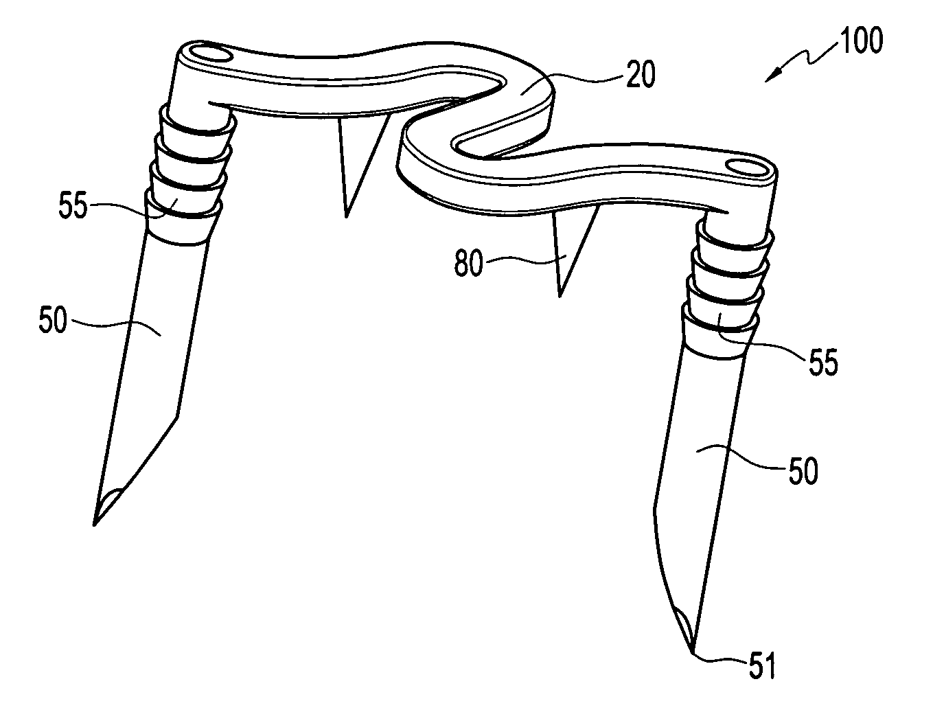
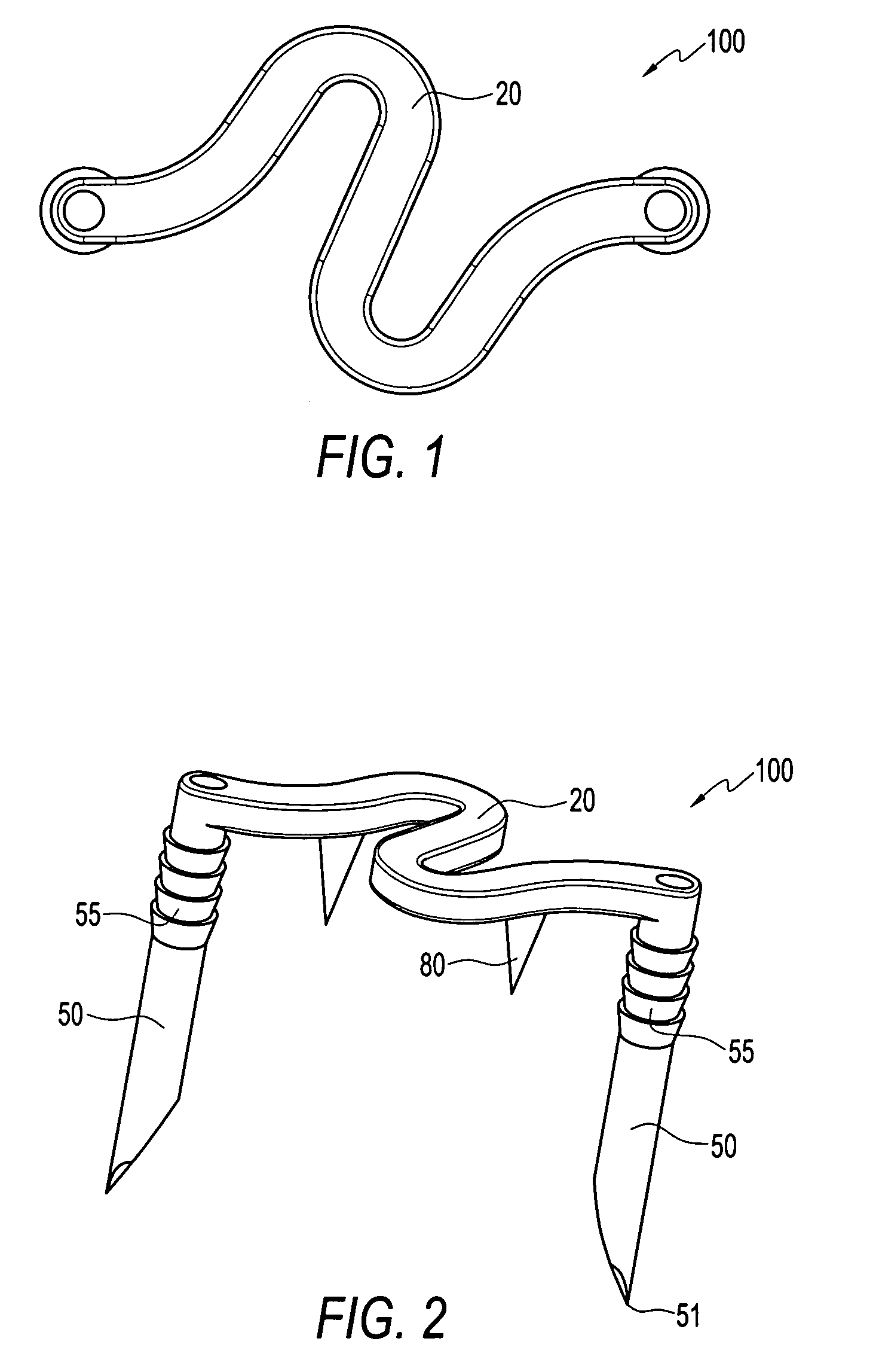
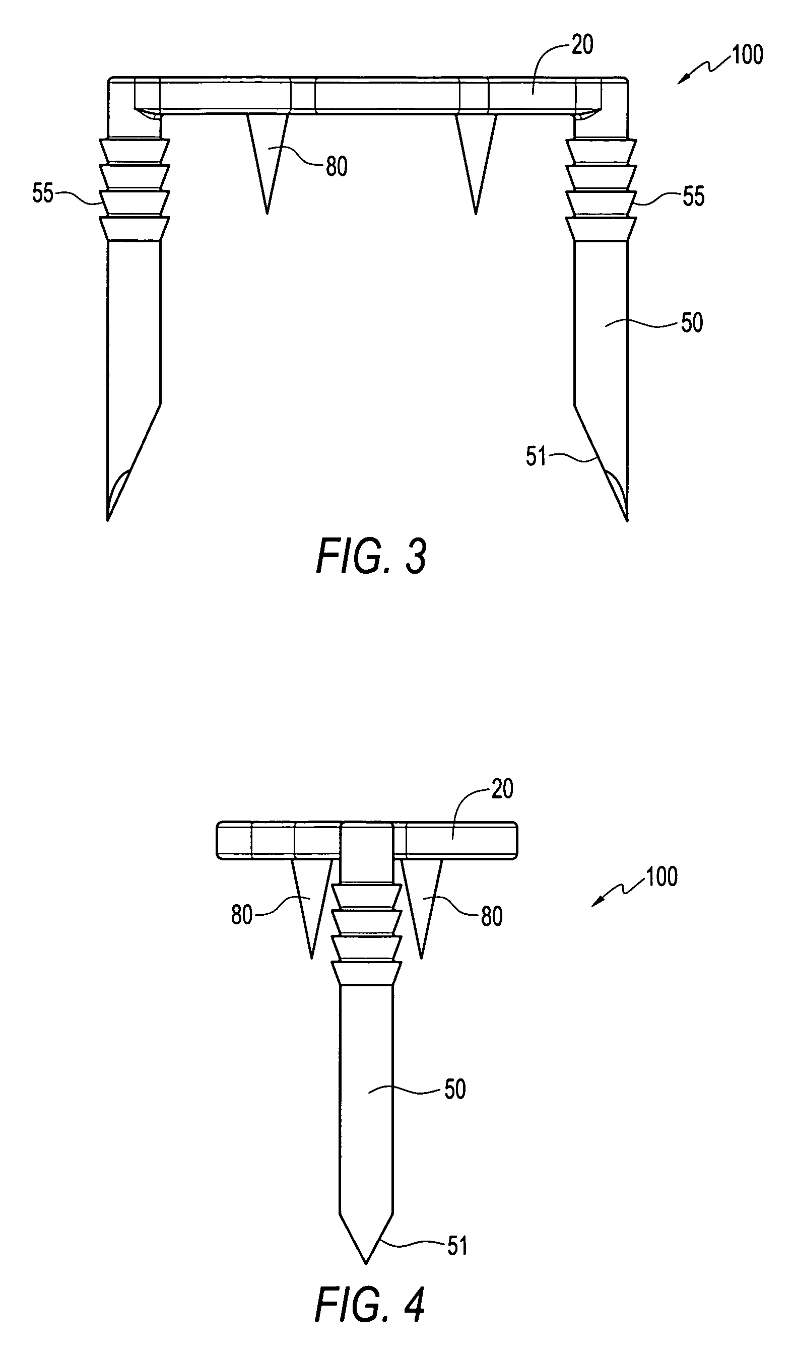
[0020]FIGS. 1-5 illustrate a compression staple 100 according to the present invention. As shown in FIGS. 1-3, the compression staple 100 comprises a central portion 20 having an S-shaped profile and two posts or legs 50 located at the bottom surface of the central portion. The S-shaped configuration of the central portion 20 provides maximum compression at a minimal material yield point while reducing the torque on the staple posts 50. As compression is a function of the distance between the staple posts before and after compression of the staple, compression is applied at the sides of the staple illustrated by arrows A in FIG. 5. The compression applied on the sides reduces the moment of ...


PUM


Abstract

A compression staple that can secure tissue (for example, bone) easily and effectively, and can provide improved fixation capabilities. The compression staple comprises a yolk or central portion having an S-shaped profile and two posts located at the bottom surface of the central portion. The two posts have a cylindrical configuration and may be cannulated. The posts may be also provided with a plurality of ribbed barbs, preferably extending about one third the length of the posts. The compression staple may additionally comprise two spikes located at the bottom surface of the central portion. The spikes are configured to increase fixation of the staple into the bone and to allow easy penetration through the cortical bone into the cancellous bone.

Description

CROSS-REFERENCE TO RELATED APPLICATIONS [0001] This application claims the benefit of U.S. Provisional Application Ser. No. 60 / 715,613, filed Sep. 12, 2005, the entire disclosure of which is incorporated by reference herein.FIELD OF THE INVENTION [0002] The present invention is directed to a compression staple for attachment of bone to bone. BACKGROUND OF THE INVENTION [0003] Treatment of a bone fracture typically involves fastening of one bone segment to the other, to stabilize and immobilize the bones for the duration of the bone consolidation process. Traditionally, bone fixation has been accomplished by a variety of devices and techniques, the more common involving the use of metallic fastening devices such as screws, connector plates, pins and clips. These methods involve the drilling of screw holes in the bone and the use of related equipment such as drill hole templates. [0004] Conventional U-shaped clips have been used for treating bone fractures, the clip legs being install...

Claims


Application Information

Patent Timeline
Patent Type & Authority Applications(United States)
IPC IPC(8): A61F2/30
CPCA61B17/0642A61B17/1227A61B2017/00862A61B2017/0645
Inventor BECKENDORF, BRANDON G.ALBERTORIO, RICARDOCICCHINELLI, LUKE D.
Owner ARTHREX
Features
  • Generate Ideas
  • Intellectual Property
  • Life Sciences
  • Materials
  • Tech Scout
  • Unparalleled Data Quality
  • Higher Quality Content
  • 60% Fewer Hallucinations
Learn More