Lubricator valve with rotational flip-flap arm

Active Publication Date: 2007-05-03
BAKER HUGHES INC
View PDF14 Cites 29 Cited by
  • Summary
  • Abstract
  • Description
  • Claims
  • Application Information

AI Technical Summary

Benefits of technology

[0009] The invention provides an improved lubricator valve arrangement for use within a wellbore to allow the passage of tools, such as perforating guns and the like, into the wellbore while it is live. The inclusion of two, independently controllable flapper-type safety valves within the lubricator valve will permit coordinated testing of fluid pressure both above and below the lubricator valve. The upper flapper valve includes a rotational flip-flap arm arrangement to positively open and close the upper flapper valve. The lower flapper valve is equipped with an integrated poppet-style pressure equalizing valve to allow the lower flapper valve to be opened more easily.
[0010] The direction of opening of the flapper valves precludes or reduces the risk debr

Problems solved by technology

The need to deploy longer logging tools or perforating guns, for example, is a limitation for surface lubricators due to the required height of the lubricator chamber.
One problem with this type of arrangement is that the flapper valves close against a valve seat that is located below the flapper valve member.
In the event that there is debris atop either flapper member that has accumulated during the pressure testing process, the flapper member(s) may be difficult to open afterward.
A further problem with conventional lubricator valves of this type is that the

Method used


Image

  • Lubricator valve with rotational flip-flap arm
  • Lubricator valve with rotational flip-flap arm
  • Lubricator valve with rotational flip-flap arm

Examples


Example

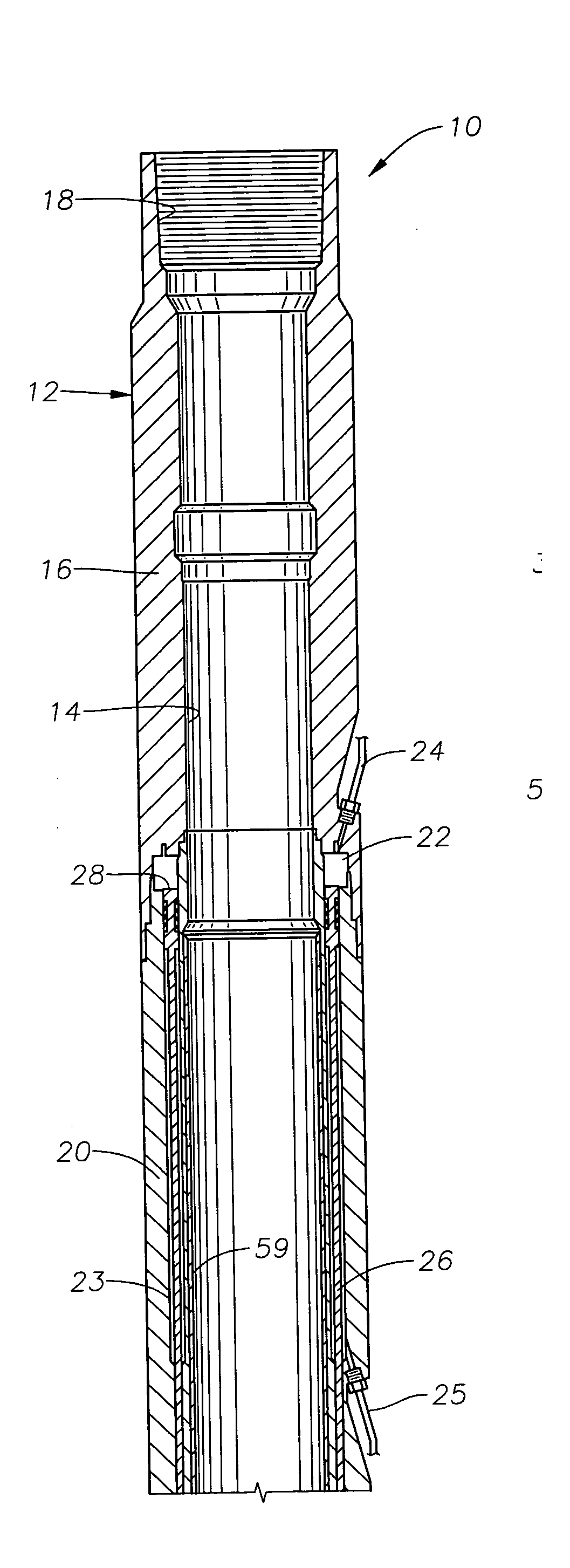
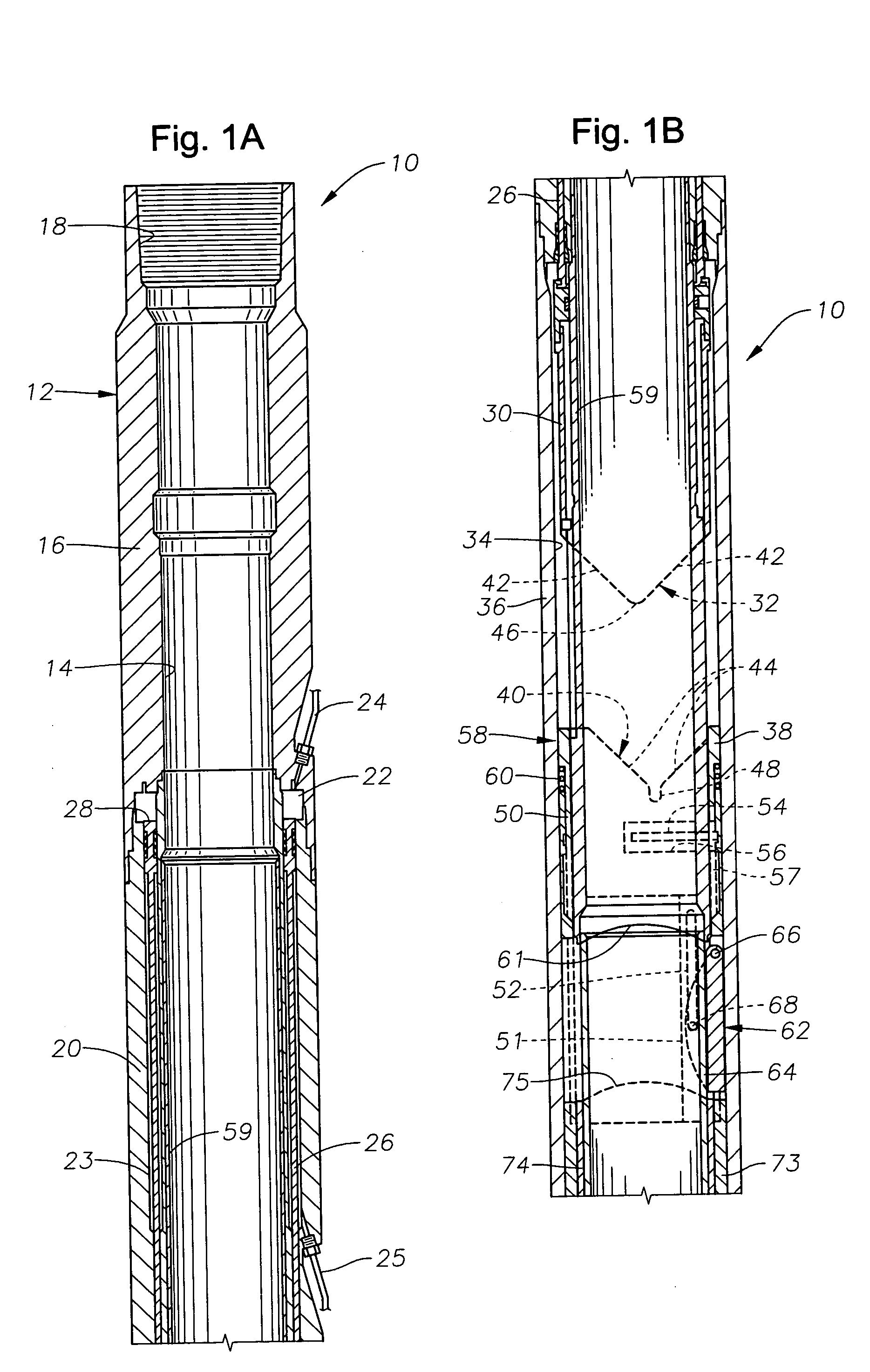
[0021] FIGS 1A-1E illustrate an exemplary downhole lubricator valve 10 that is constructed in accordance with the present invention. The valve 10 includes a valve body 12 that defines a flowbore 14 axially therethrough. Beginning at the upper end, shown in FIG. 1A, the valve body or housing 12 has an upper valve nipple 16 with a threaded box-type connection 18. The upper valve nipple 16 is affixed at its lower end to an upper piston sub 20. An annular fluid chamber 22 is defined between the upper valve nipple 16 and the upper piston sub 20. A first hydraulic “open” line 24 runs from a manifold (not shown) into the fluid chamber 22. The fluid chamber 22 is in hydraulic communication with a piston chamber 23 that is defined within the body of the upper piston sub 20. A hydraulic “close” line 25 extends into the lower end of the piston chamber 23. Similar open and close lines 24, 25 will be associated with a lower flapper valve, as will be described shortly.

[0022] An annular piston 26...


PUM


Abstract

An improved lubricator valve arrangement for use within a wellbore to allow the passage of tools, such as perforating guns and the like, into the wellbore while it is live. The inclusion of two, independently controllable flapper-type safety valves within the lubricator valve will permit coordinated testing of fluid pressure both above and below the lubricator valve. The upper flapper valve includes a rotational flip-flap arm arrangement to positively open and close the upper flapper valve. The lower flapper valve is equipped with an integrated poppet-style pressure equalizing valve to allow the lower flapper valve to be opened more easily. The direction of opening of the flapper valves precludes or reduces the risk debris-related problems that might prevent or hinder opening of the flapper valves.

Description

CROSS-REFERENCE TO RELATED APPLICATIONS [0001] This application is a continuation-in-part of U.S. patent application Ser. No. 11 / 099,938 entitled “Flapper Opening Mechanism” filed Apr. 6, 2005. BACKGROUND OF THE INVENTION [0002] 1. Field of the Invention [0003] The invention relates generally to the design of lubricator valves used for installing tools in a live oil or gas well on wireline while controlling fluids therethrough. [0004] 2. Description of the Related Art [0005] During operation of live oil or gas wells, it is sometimes necessary to run a tool, such as a perforating gun, into the well. Because the well is live, it may be under pressure and, therefore, it is necessary to use a device known as a lubricator valve to allow passage of the tool while controlling the flow of pressurized fluid. Sometimes the lubricator valve is located at the surface, above the wellhead. A surface-based lubricator valve is a pressure-retaining container that is used to hold the wireline tool st...

Claims


Application Information

Patent Timeline
IPC IPC(8): E21B34/10
CPCE21B33/068E21B34/102E21B34/14E21B2034/005E21B2200/05
Inventor FARQUHAR, GRAHAM E.HARDIE, DAVID A.
Owner BAKER HUGHES INC
Why Eureka
Try Eureka