Fastener engaging caulking tube nozzle

Inactive Publication Date: 2007-05-03
CHICK MARK C
View PDF22 Cites 13 Cited by
  • Summary
  • Abstract
  • Description
  • Claims
  • Application Information

AI Technical Summary

Benefits of technology

[0009] This invention makes it possible to extract any hardened caulk and properly expose the usable caulking, as often found in previously open tubes of caulk. The upper portion of the caulk tube and nozzle can be detached by unscrewing or unlocking it from the main body of the tube. After the upper portion or cylinder has been separated, from the main body of the caulk tube, the worker has access to clean the dried matter from both the upper portion of the tube, and including from within the nozzle, and be allowed to remove the dried matter from both the upper portion of the tube including the nozzle, and thereby to clear the main body of the tube for further dispensing of caulk under pressure, during usage of the caulking gun. The upper portion of the caulk tube is secured to the main body of the tube by threads or a twist lock. Such fastening means can be located on the main tube, and the upper portion of the tube, including the nozzle, so that secure fastening can be made, and so it will not leak, particularly when the caulking tube is subjected to extensive pressure, during usage of the gun. Any silicone butyl rubber caulk will harden beyond the nozzle and into the actual tube, depending upon the amount of time that has elapsed since the initial seal was punctured. Since the upper portion of the tube can be easily removed, cleaned, and reattached, it makes it possible to extract that undamaged caulking or materials from the original nozzle.
[0010] It is, therefore, the principal object of this invention to provide a caulking tube nozzle that can be threadedly or otherwise engaged to the upper end of the caulking tube, so that it may be readily removed, and replaced, or simply cleaned out, during usage.
[0013] Still another object of this invention is to provide a replacement for a caulking tube that may be very quickly and easily applied, or removed for cleaning, thereby eliminating the need to throw away half used tubes of caulk that may still have a substantial amount of fresh and pliable caulk therein, but cannot be otherwise dispensed because of blockage.

Problems solved by technology

It is of concern that if the lip portion of the nozzle is too thick, and it is threadely engaged externally of the upper end of the caulking tube, that the nozzle, with its base and lip, may not fit within the standard caulking gun, for usage.

Method used


Image

  • Fastener engaging caulking tube nozzle
  • Fastener engaging caulking tube nozzle

Examples


Embodiment Construction

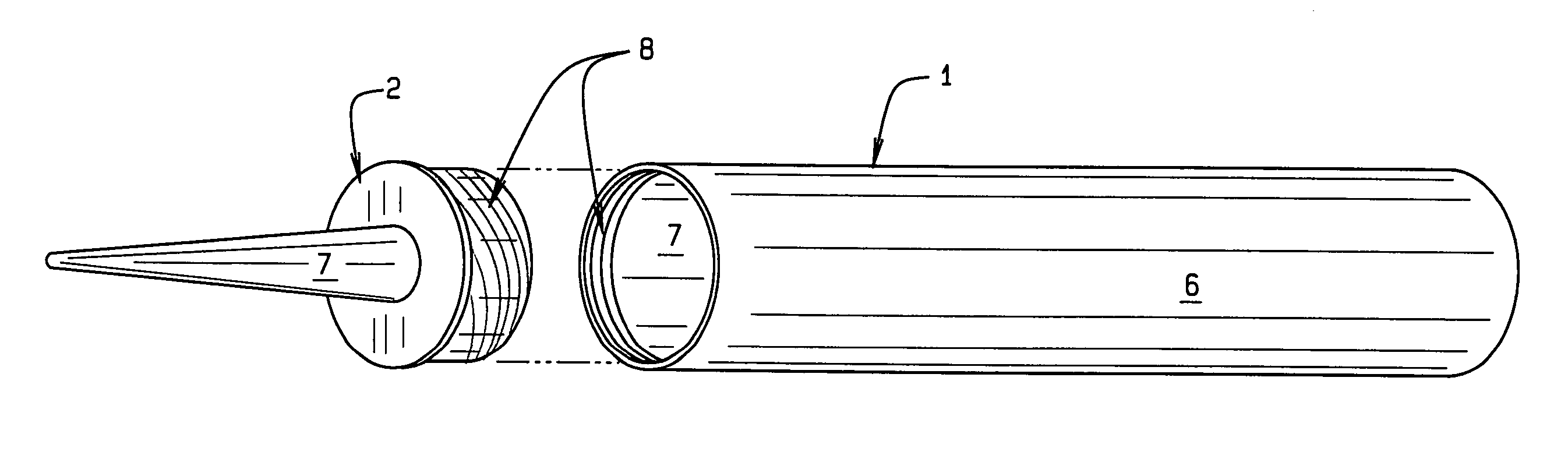
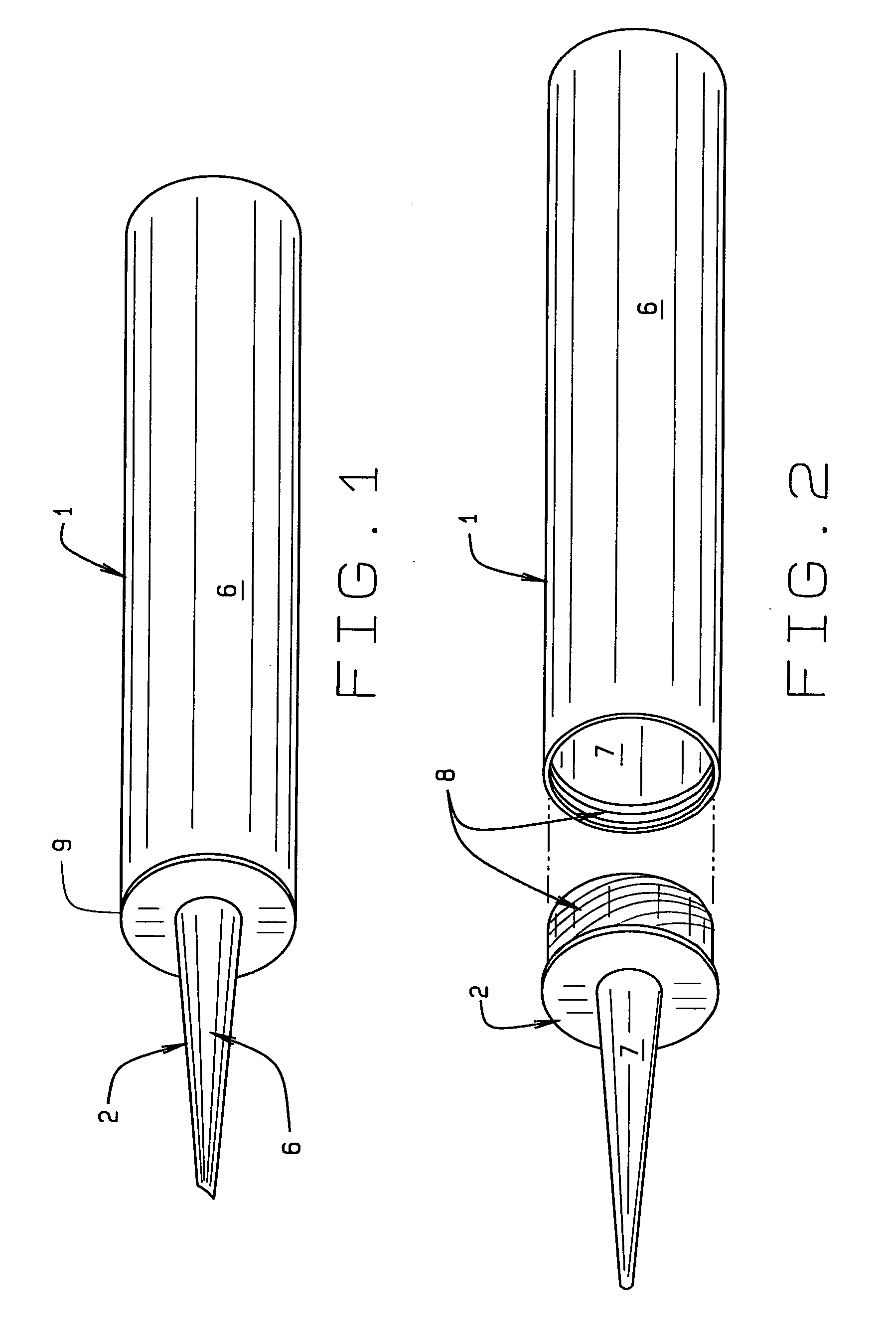
[0017] In referring to the drawings, and in particular FIG. 1, therein is shown a typical cartridge containing caulk or other material 6. Normally, this is a cylinder or tube 1, which holds the supply of caulk, in preparation for usage. The cylinder 1 includes an integrated nozzle 2, onto the top of the standard type of tube, for application to a caulking gun. After the nozzle 2 has been initially cut, and material 6 has been forced from the tube, during usage, as through the nozzle 2, there is normally some remaining amount of material that is left within the upper portion of the tube, and its nozzle, after usage. After prolonged storage, such caulking material can become reasonably hardened, over time, making it impossible to force the remaining material 6 through the nozzle 2, during subsequent usage.

[0018] As can also be seen, the integrated nozzle 2 has a flange 9 that extends out to embrace the upper edge of the tube 1, so as to provide for further sealing at that location, w...


PUM


Abstract

Caulking tube nozzle, having a nozzle portion, with an integral base, and having a lip connecting and extending downwardly therefrom, the lip is intended for inserting within the upper end of the caulking tube, and is threadedly engaged, held by a bayonet lock, or other fastener, therein, so that the nozzle can be held in place during usage, or opened for removal of any hardened material, before usage. The base of the nozzle may also under certain circumstances engage externally of the upper end of the caulking tube.

Description

CROSS REFERENCE TO RELATED APPLICATION [0001] This nonprovisional patent application claims priority to the provisional patent application having Ser. No. 60 / 740,609, filed on Nov. 29, 2005; this application is also a continuation-in-part application which claims priority to the regular letters patent application having Ser. No. 11 / 261,207, which was filed on Oct. 28, 2005, which claims priority to the regular letters patent application having Ser. No. 10 / 407,707, which was filed on Apr. 4, 2003, which claims priority to the provisional patent application having Ser. No. 60 / 370,765, which was filed on Apr. 9, 2002.BACKGROUND OF THE INVENTION [0002] This invention relates primarily to a caulking tube, for use with a caulking gun, and more specifically pertains to fastener engaged caulking tube nozzle. [0003] This invention further relates to the caulking tube, wherein its nozzle portion can be installed, or replaced, particularly, after the factory installed nozzle and tube may becom...

Claims


Application Information

Patent Timeline
IPC IPC(8): B65D35/38B65D88/54
CPCB05C17/00513B05C17/00596
Inventor CHICK, MARK C.
Owner CHICK MARK C
Why Eureka
Try Eureka