Power source and electronic device assembly

Inactive Publication Date: 2009-12-31
CHANNEL PROD INC
View PDF1 Cites 0 Cited by
  • Summary
  • Abstract
  • Description
  • Claims
  • Application Information

AI Technical Summary

Benefits of technology

[0004]The present invention solves the problems with prior art assemblies involving housings for power sources and their associated electronic devices, and other problems, by providing a housing for a power source that can be readily removed and replaced without the use of tools and wherein the overall assembly of the housing and its associated electronic device is sealed to the environment. The housing for the power source of the present invention is comprised of a casing member that receives at least one dry cell battery and an electrical conductor having a contact spring portion that engages the positive terminal of the bottom-most battery adjacent the closed end of the casing member and an oppositely disposed terminal end portion that contacts one of oppositely disposed interconnected terminals in the electronic device. The oppositely disposed open end of the casing member has male threads provided thereon which engage male threads within the electronic device. A centrally located terminal in the electronic device engages the negative terminal on the upper-most battery. By inserting the end of the casing member into a recess in the ele

Problems solved by technology

Since the electronic device is mounted on the underside of the appliance and is not visible unless one looks under the appliance, replacement of the batteries is a relatively difficult task since the person replacing the batteries must go under the applianc

Method used


Image

  • Power source and electronic device assembly
  • Power source and electronic device assembly
  • Power source and electronic device assembly

Examples


Example

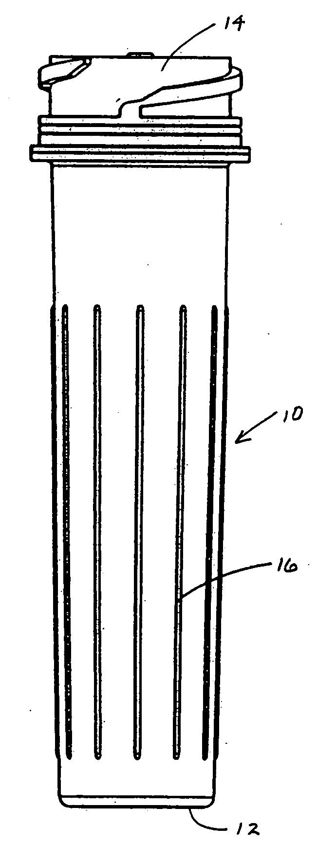
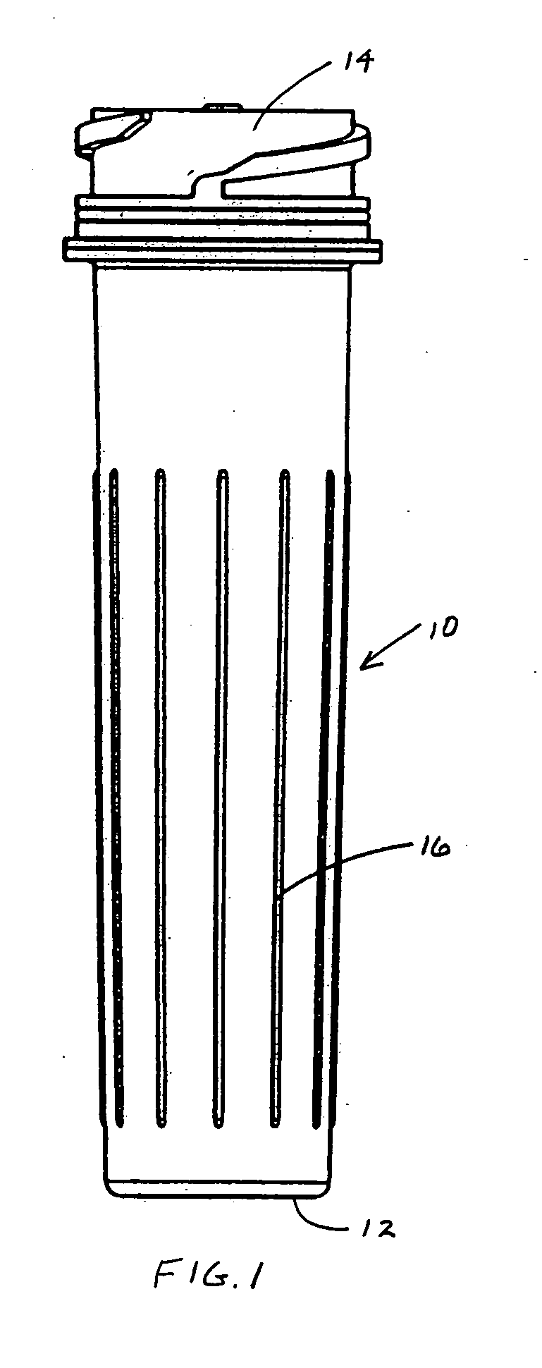
[0010]Referring now to the drawings where the illustrations are for the purpose of describing the preferred embodiment of the present invention and are not intended to limit the invention described herein, FIG. 1 is a front elevation view of the casing member 10 of the present invention. The casing 10, which can be made from any one of a number of injection moldable plastic materials, may be tubular in configuration and have a closed end 12 and an oppositely disposed open end 14. The overall length of casing 10 is sufficient to accommodate at least one dry cell battery and the inner diameter thereof is sized to receive such batteries. A plurality of spaced-apart longitudinally extending ribs 16 are provided on the outer surface of casing 10 to assist in the gripping of same when attaching or removing the casing to or from an associated electronic device, as hereinafter described. The ribs 16 are substantially parallel to one another and oriented such that adjacent ribs 16 are substa...


PUM


Abstract

An assembly comprising a casing for a power source and an associated electronic device is disclosed. The casing receives at least one dry cell battery and an electrical conductor having a contact spring portion that engages the bottom-most battery. The upper end of the casing has threads provided thereon which engage threads within the electronic device. A centrally located terminal in the electronic device engages the negative terminal on the upper-most battery and one of its oppositely disposed interconnected terminals engage the terminal end portion of the electrical conductor whose contact spring portion engages the negative terminal on the bottom-most battery. By inserting the open end of the casing into a recess in the electronic device and then rotating the casing by about 90 degrees with respect to the electronic device, the threads on the casing engage the threads on the electronic device securing the casing to the electronic device and causing the negative terminal on the upper-most battery in the casing to engage the central terminal in the electronic device and causing the terminal end portion of the electrical conductor whose contact spring portion engages the positive terminal on the bottom most-battery in the casing to engage one of the oppositely disposed interconnected terminals in the electronic device. The structure of the casing permits the easy removal and replacement of same with respect to the electronic device and also provides an overall assembly that is sealed to the environment and is watertight and submersible.

Description

TECHNICAL FIELD[0001]The present invention relates, in general, to an assembly comprising a housing for a power source and an associated electronic device and, more particularly, to such an assembly wherein the housing for the power source can be readily and easily changed and the assembly is environmentally sealed to weather conditions and is watertight and submersible.BACKGROUND ART[0002]Electronic devices for an appliance may be powered by dry cell batteries. These electronic devices are usually mounted on the underside of the appliance and are not visible unless one looks under the appliance. The batteries for these electronic devices are usually received within a recess in the device. Since the electronic device is mounted on the underside of the appliance and is not visible unless one looks under the appliance, replacement of the batteries is a relatively difficult task since the person replacing the batteries must go under the appliance in order to remove and replace same. In...

Claims


Application Information

Patent Timeline
IPC IPC(8): H01M2/10H01M50/107H01M50/184H01M50/186H01M50/193
CPCH01M2/022H01M2/105H01M2/08H01M2/024Y02E60/10H01M50/107H01M50/213H01M50/184H01M50/186H01M50/193
Inventor BLUHM, THOMAS K.ADAMS, TERRENCE M.
Owner CHANNEL PROD INC
Why Eureka
Try Eureka