Brake Cooling Fan and Method of Use

Inactive Publication Date: 2012-07-12
ROBERTSON JERRY
View PDF8 Cites 7 Cited by
  • Summary
  • Abstract
  • Description
  • Claims
  • Application Information

AI Technical Summary

Benefits of technology

[0014]In accordance with the present invention, a brake-cooling device is provided for a motor vehicle having a wheel with a wheel hub, and a disc brake assembly. The brake-cooling device consists of a first fan blade with blade leaves that move air while the first fan blade is in motion. The first fan blade is secured onto the wheel hub on an outside-facing side of the wheel hub. Because the brake-cooling device is positioned on the outside-facing side

Problems solved by technology

For example, a brake duct can suffer a blockage during a race,

Method used


Image

  • Brake Cooling Fan and Method of Use
  • Brake Cooling Fan and Method of Use
  • Brake Cooling Fan and Method of Use

Examples


Example

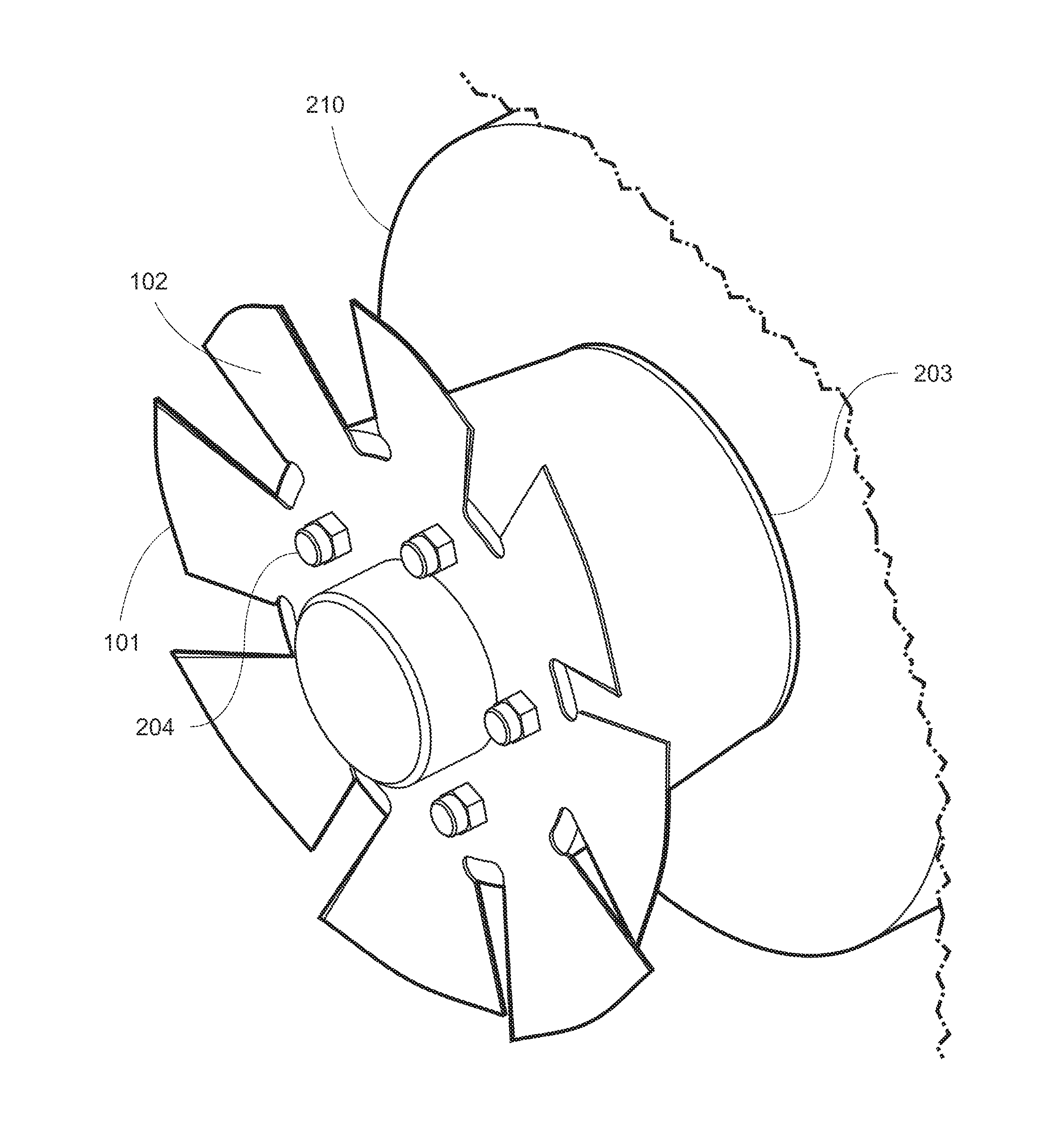
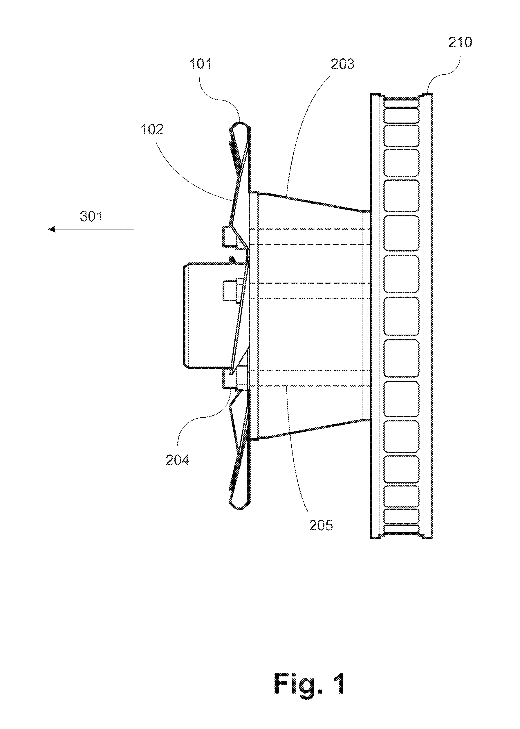
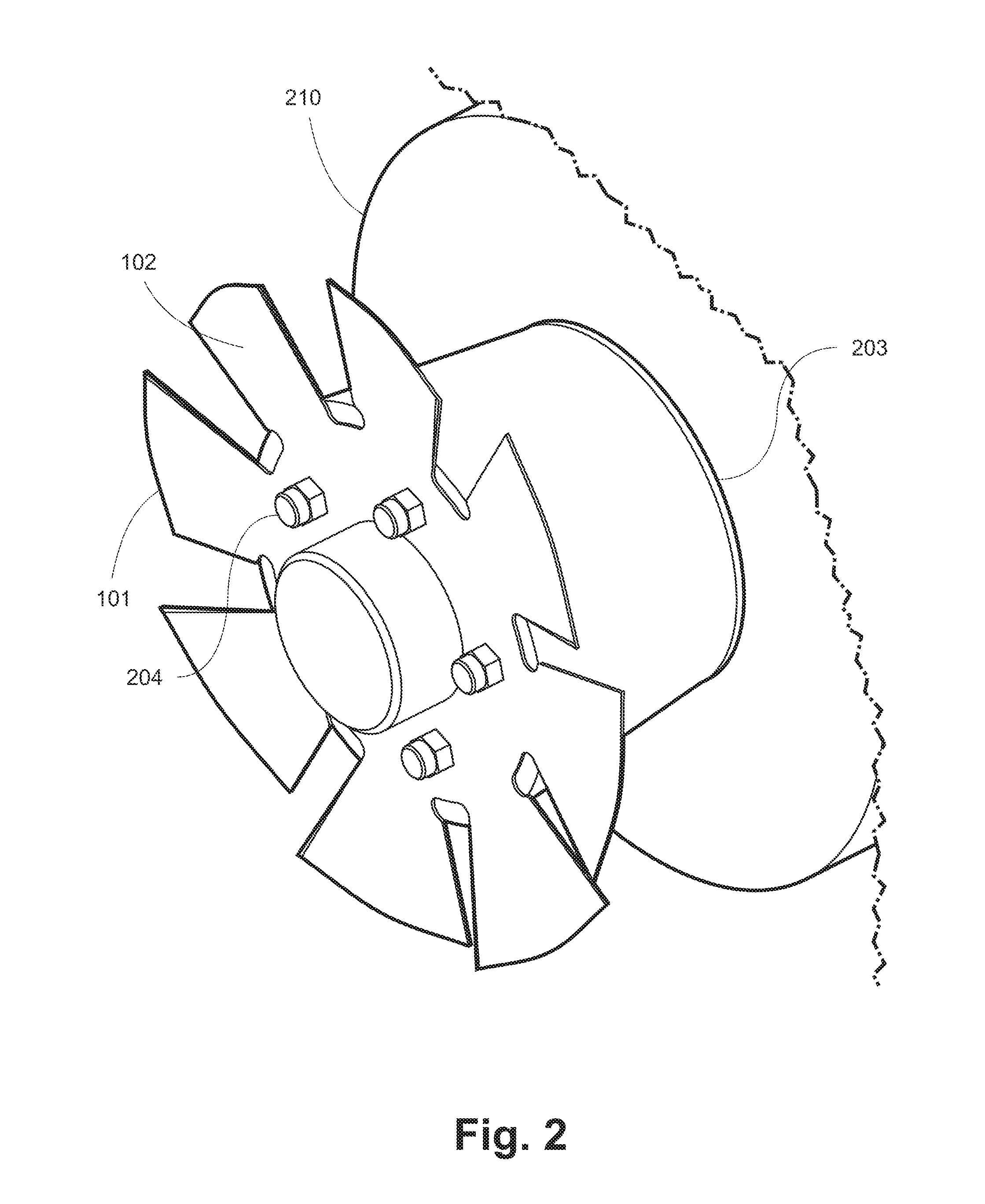
[0026]In a motor vehicle, the brake rotor 210 generates and accumulates heat during the operation of the brakes (not shown). To dispel this heat, cool air is typically blasted at the brake rotor 210 using devices such as brake ducts (not shown). The heat is transferred from the brake rotor 210 to the cool air and the resulting warm air is expelled away from the brake rotor 210.

[0027]FIG. 1 and FIG. 2 show the fan blade 101 that is used as part of an embodiment of the present invention. The fan blade 101, the wheel hub 203, and the brake rotor 210 are secured together by lug nuts 204 and wheel bolts 205. On an operational motor vehicle, the wheel (not shown) would also secured by the lug nuts 204 and the wheel bolts 205 on the outer side of the fan blade 101, opposite the wheel hub 203. During operation of the motor vehicle, the fan blade 101 turns as the wheel turns. As the fan blade 101 turns, the blade leaves 102 of the fan blade 101 force the warm air outward in a direction 301 g...


PUM

PropertyMeasurementUnit
Timeaaaaaaaaaa

Abstract

A brake-cooling device is provided for a motor vehicle having a wheel with a wheel hub, and a disc brake assembly. The brake-cooling device consists of a first fan blade with blade leaves that move air while the first fan blade is in motion. The first fan blade is secured onto the wheel hub on an outside-facing side of the wheel hub. Because the brake-cooling device is positioned on the outside-facing side of the wheel hub (rather than within the disc brake assembly, for example), the brake-cooling device can be readily removed or replaced as necessary. The present invention is also designed such that the first fan blade can be stacked with additional fan blades or with other wheel accessories without interfering with the operation of the wheel (e.g., some embodiments of the invention does not require the wheel offsets to be changed) or disc brake assembly.

Description

FIELD OF THE INVENTION[0001]The invention relates to a technology for cooling motor vehicle wheels equipped with disc brakes.BACKGROUND OF THE INVENTION[0002]It is well known in the automotive brake art to use devices such as ventilated brake rotors, fan blades, and specialty wheel trims to improve the heat transfer to the ambient air.[0003]During the conventional operation of motor vehicle brakes, heat is generated in the brake rotor as the kinetic energy of the moving vehicle is converted to heat energy as brake pads are applied to the brake rotor. The buildup of heat in the brake rotor can lead to unequal temperature distribution in the brake rotor, causing it to warp and deteriorate.[0004]A complication associated with this buildup of heat is that the heated air surrounding the brake rotor decreases the vehicle's aerodynamics. Given its location in the undercarriage of the vehicle, the brake rotor (and its associated wheel assembly) creates a high-pressure air pocket underneath ...

Claims


Application Information

Patent Timeline
IPC IPC(8): F16D65/847B23P11/00
CPCY10T29/49826F16D65/847
Inventor ROBERTSON, JERRY
Owner ROBERTSON JERRY
Why Eureka
Try Eureka