Aircraft Thrust Bearing Assembly, Method of Manufacture and Method of Use

Inactive Publication Date: 2010-10-21
MELYON SOLLY +1
View PDF18 Cites 1 Cited by
  • Summary
  • Abstract
  • Description
  • Claims
  • Application Information

AI Technical Summary

Benefits of technology

[0030]Accordingly, a feature and advantage of the present invention is its ability to adapt a propeller to an existing engine while providing support to the propeller and while reducing deteriorative forces on the engine.
[0031]Another feature and advantage of the present invention is its ability to be readily removed and replaced within its housing.
[0032]Still another feature and advantage of the

Problems solved by technology

Unfortunately, this direct drive construction, coupled with aircraft maneuvers, may result in gyroscopic, asymmetric and bending loads (as opposed to t

Method used


Image

  • Aircraft Thrust Bearing Assembly, Method of Manufacture and Method of Use
  • Aircraft Thrust Bearing Assembly, Method of Manufacture and Method of Use
  • Aircraft Thrust Bearing Assembly, Method of Manufacture and Method of Use

Examples


Example

[0043]In describing the preferred embodiment of the present invention, as illustrated in FIGS. 1-6, specific terminology is employed for the sake of clarity. The invention, however, is not intended to be limited to the specific terminology so selected, and it is to be understood that each specific element includes all technical equivalents that operate in a similar manner to accomplish similar functions.

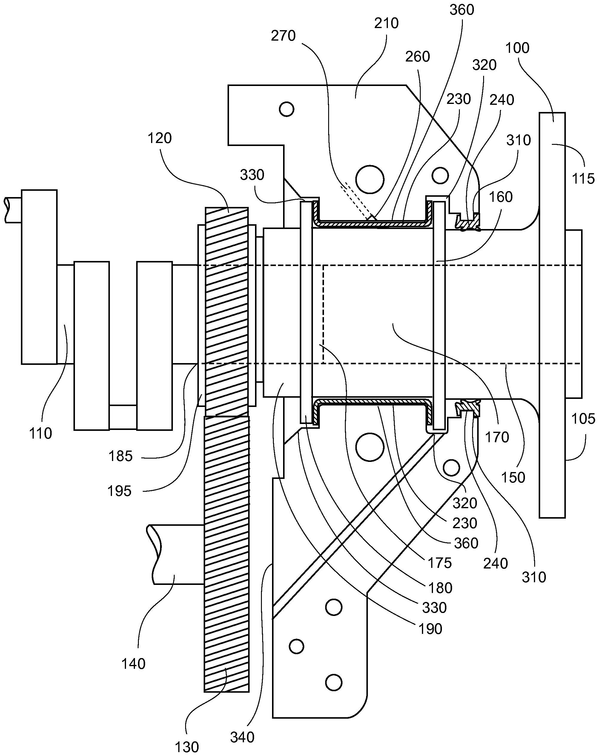
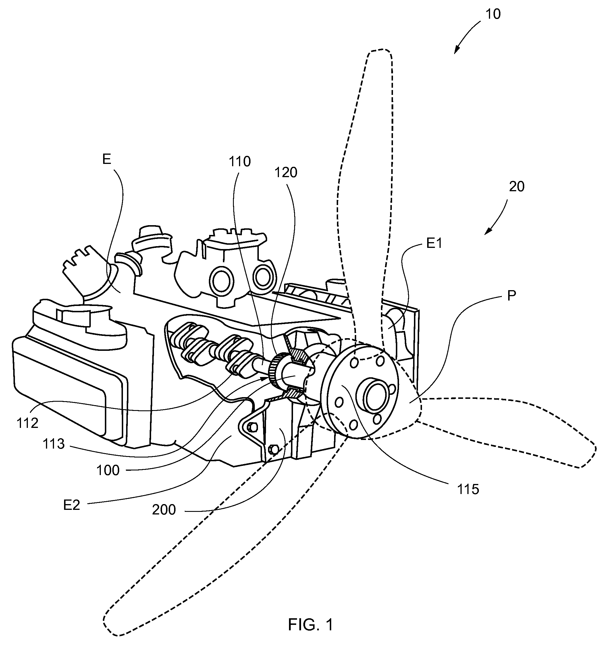
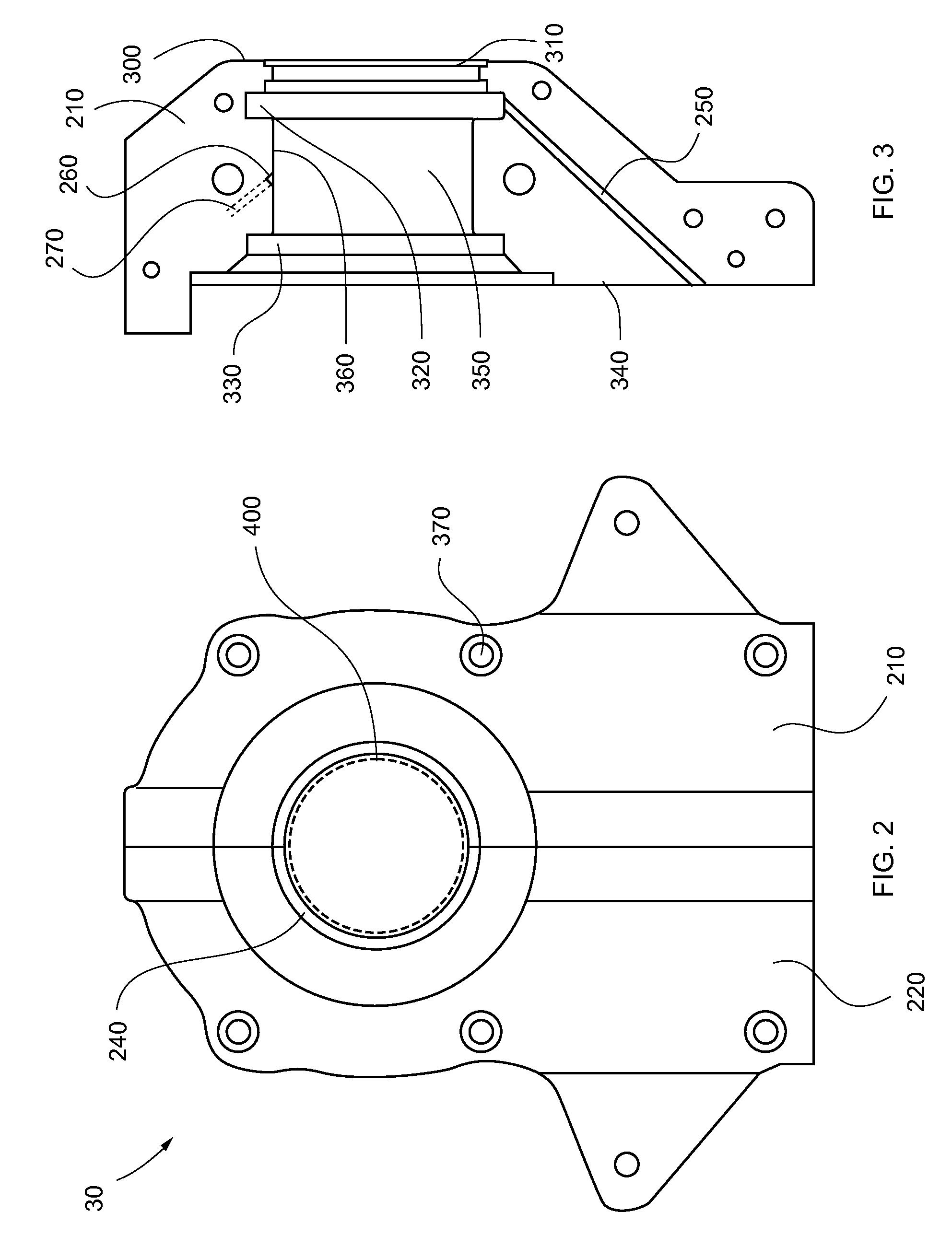
[0044]Referring now to FIGS. 1-6, the present invention in a preferred embodiment is aircraft engine 10 with thrust bearing assembly 20, a method of manufacture and a method of use, wherein aircraft thrust bearing assembly 20 comprises thrust bearing shaft 100, U-shaped bearing 230, oil seal 240, housing 30 and gear 120, and wherein thrust bearing shaft 100 comprises mounting plate 115 for propeller P, and wherein propeller P is secured to front 105 of mounting plate 115 via suitable fasteners as are known in the art for securing aircraft propellers to thrust bearings.

[0045]Thrust be...


PUM


Abstract

An aircraft thrust bearing assembly utilizing a U-shaped bearing disposed over a portion of a thrust bearing shaft, both within a housing that is mounted to the front of an engine utilized for driving an aircraft propeller. The thrust bearing shaft rides in the U-shaped bearing, wherein the U-shaped bearing separates the thrust bearing shaft from the housing. The front of the thrust bearing shaft has a mounting plate for attachment of a propeller, the mounting plate being machined to be perpendicular to the rotational axis of the thrust bearing shaft. The rear of the thrust bearing shaft comprises an outer surface adapted to receive a gear press-fitted thereon and an aperture within the shaft that is dimensioned to fixedly receive therewithin an end portion of the crankshaft of the engine being selected for propulsion of the aircraft.

Description

FEDERALLY SPONSORED RESEARCH OR DEVELOPMENT[0001]NonePARTIES TO A JOINT RESEARCH AGREEMENT[0002]NoneREFERENCE TO A SEQUENCE LISTING[0003]NoneBACKGROUND OF THE INVENTION[0004]1. Technical Field of the Invention[0005]The present invention relates generally to thrust bearings for aircraft engines, and more specifically to a thrust bearing with housing for installation on the crankshaft of an engine for an experimental aircraft.[0006]2. Description of Related Art[0007]Many aircraft enthusiasts enjoy and even prefer to construct their own aircraft, which are typically known as experimental aircraft. Often such aircraft utilize standard aircraft engines, but occasionally, other non-aircraft engines may be utilized.[0008]Due to the need to simplify construction and cost, such enthusiast aircraft typically utilize air-cooled engines, rather than those cooled by glycol or other fluids. Accordingly, engines selected for use will often be chosen from the selection of available automotive air-c...

Claims


Application Information

Patent Timeline
IPC IPC(8): F16C9/02B21D53/10
CPCF16C9/02Y10T29/49645F16C35/02
Inventor MELYON, SOLLYCLAPP, WILLIAM M.
Owner MELYON SOLLY
Why Eureka
Try Eureka