Pivoting baggage rack intended for an aircraft cabin

a baggage rack and aircraft cabin technology, applied in aircraft accessories, aircraft crew accommodation, fuselages, etc., can solve the problems of limited volume inside the aircraft cabin and limited dimensions, and achieve the effect of simple implementation

Active Publication Date: 2007-05-03
AIRBUS
View PDF13 Cites 26 Cited by
  • Summary
  • Abstract
  • Description
  • Claims
  • Application Information

AI Technical Summary

Benefits of technology

[0016] In such an aircraft cabin, an air vent extending along the rear portion of the lower outer face of a baggage rack can be provided, and this air vent has a movable flap at its outlet, for example. In this way, the outlet surface of the air vent can remain constant by subjugating the position of the flap to that of the baggage rack. In an advantageous embodiment, f

Problems solved by technology

However, the volume inside an aircraft cabin is limited.
Moreover, as regards the baggage racks and bins, their dimensions are limited inasmuch as the s

Method used


Image

  • Pivoting baggage rack intended for an aircraft cabin
  • Pivoting baggage rack intended for an aircraft cabin

Examples


Embodiment Construction

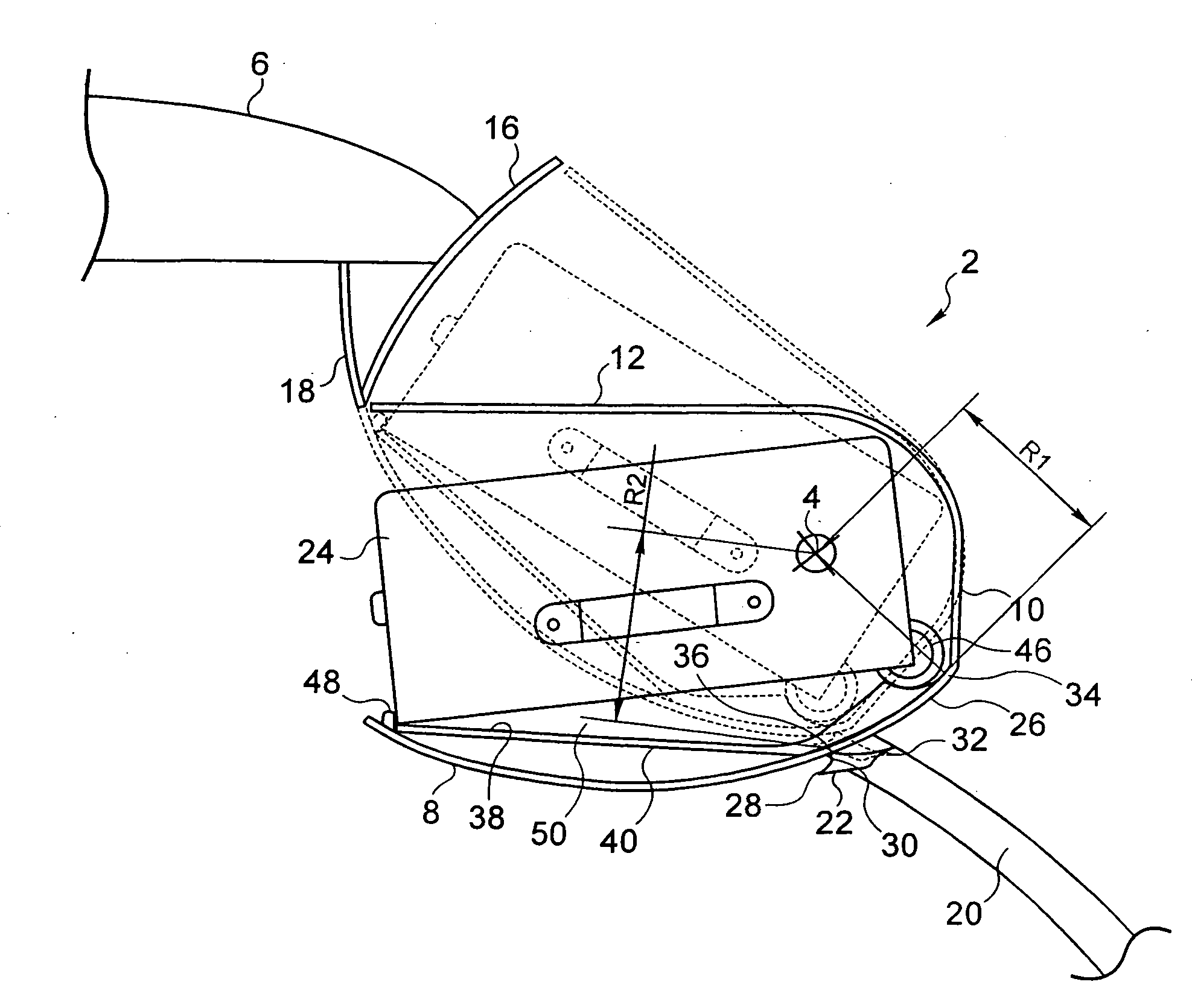
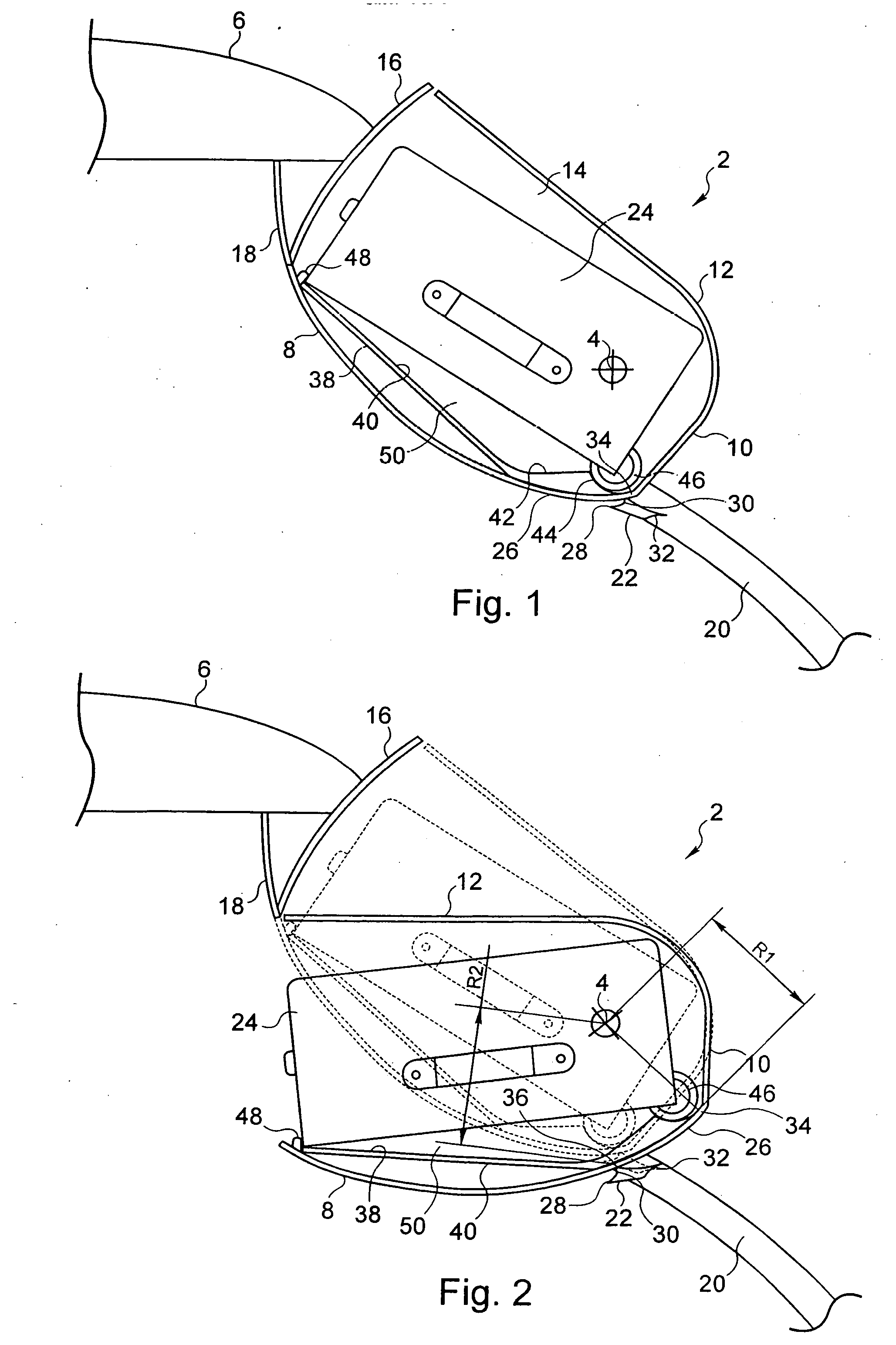
[0022] The baggage rack 2 depicted in the drawings is a rack mounted pivoting around an axis of pivoting 4. Here it is a matter of a baggage rack 2 mounted in an aircraft cabin. This rack is mounted in the upper portion of this cabin, above the passenger seats, not depicted. The axis of pivoting 4 is a longitudinal axis in relation to the aircraft cabin. The ceiling 6 of this cabin is recognizable on the drawings.

[0023] The baggage rack 2 comprises a lower outer face 8, a back 10, an upper face 12 and lateral walls 14. The overall shape of this rack is more or less parallelepipedal with a rounded lower face. The face opposite the back 10 is a completely open face.

[0024] On FIG. 1, the baggage rack 2 is depicted in its closed position. It then is retracted in the ceiling 6 of the aircraft cabin. Inside this ceiling, a fixed flap 16 comes to close the open face of the baggage rack, opposite the back 10. This fixed flap 16 takes on, for example, as depicted in the drawings, the form ...


PUM


Abstract

A baggage rack includes a compartment having a lower outer face, an upper face, an open face allowing access to the compartment, as well as a back. The rack is mounted pivoting around an axis of pivoting between an open position in which the open face of the compartment is accessible and in which a rear portion of the lower outer face is concealed, and a closed position in which the open face of the compartment is retracted and in which the rear portion of the lower outer face is visible. The rear portion has a cylindrical form including generatrices substantially parallel to the axis of pivoting of the rack, and the distance from the axis of pivoting to the generatrices is increasing from the back of the compartment toward the open face of the latter.

Description

CROSS-REFERENCE TO RELATED APPLICATIONS [0001] This document claims priority to French Application Number 05 11028, filed Oct. 28, 2005 and U.S. Provisional Application No. 60 / 750,034, filed Dec. 14, 2005, the entire contents of which are hereby incorporated by reference.BACKGROUND OF THE INVENTION [0002] 1. Field of the Invention [0003] This invention relates to a baggage rack intended for an aircraft cabin. [0004] The field of this invention is the transport of passengers in an aircraft. During a trip, the travelers' baggage is placed in the holds of the aircraft, while lighter baggage can accompany the travelers in the aircraft cabin. In this cabin, storage spaces are provided for this baggage, also referred to as hand baggage. More often than not, these storage spaces are arranged in the upper portion of the aircraft cabin, beneath the ceiling of this cabin and above the seats intended to accommodate the passengers. [0005] 2. Description of the Related Art [0006] There are two m...

Claims


Application Information

Patent Timeline
IPC IPC(8): B64D47/00
CPCB64D11/003
Inventor BOCK, THOMAS-MATHIAS
Owner AIRBUS
Why Eureka
Try Eureka