Paper post processing apparatus

Inactive Publication Date: 2007-05-03
KYOCERA DOCUMENT SOLUTIONS INC +1
View PDF7 Cites 13 Cited by
  • Summary
  • Abstract
  • Description
  • Claims
  • Application Information

AI Technical Summary

Benefits of technology

[0024] With this structure, when the second stoppers move, they are prevented from interfering with the edge of the paper stack, and this permits the second stoppers to move smoothly and also permits the paper stack to be kept aligned, and hence the stapling means can perform stapling with enhanced accuracy.
[0025] According to the present invention, in the paper post processing apparatus structured as described above, at an end of each of the second stoppers, a paper receiving portion is formed for aligning an edge of a paper stack, the second stoppers are supported so as to be slidable in a direction perpendicular to a paper transport direction along a guide axis fixed to a frame inside a main body of the app

Problems solved by technology

However, in any of the apparatuses disclosed in JP-A-H10-338412, JP-A-H9-142724, and JP-A-H9-86778, since the stapler body and the stoppers are built as separate units, it is difficult, when the stapler or the stoppers is moved, to maintain an accurate positional relationship among them, and

Method used


Image

  • Paper post processing apparatus
  • Paper post processing apparatus
  • Paper post processing apparatus

Examples


first embodiment

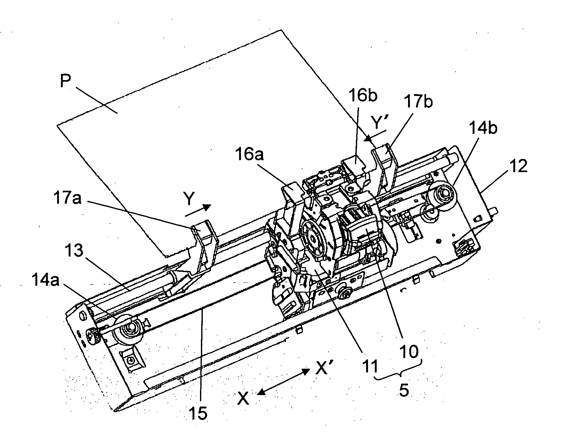
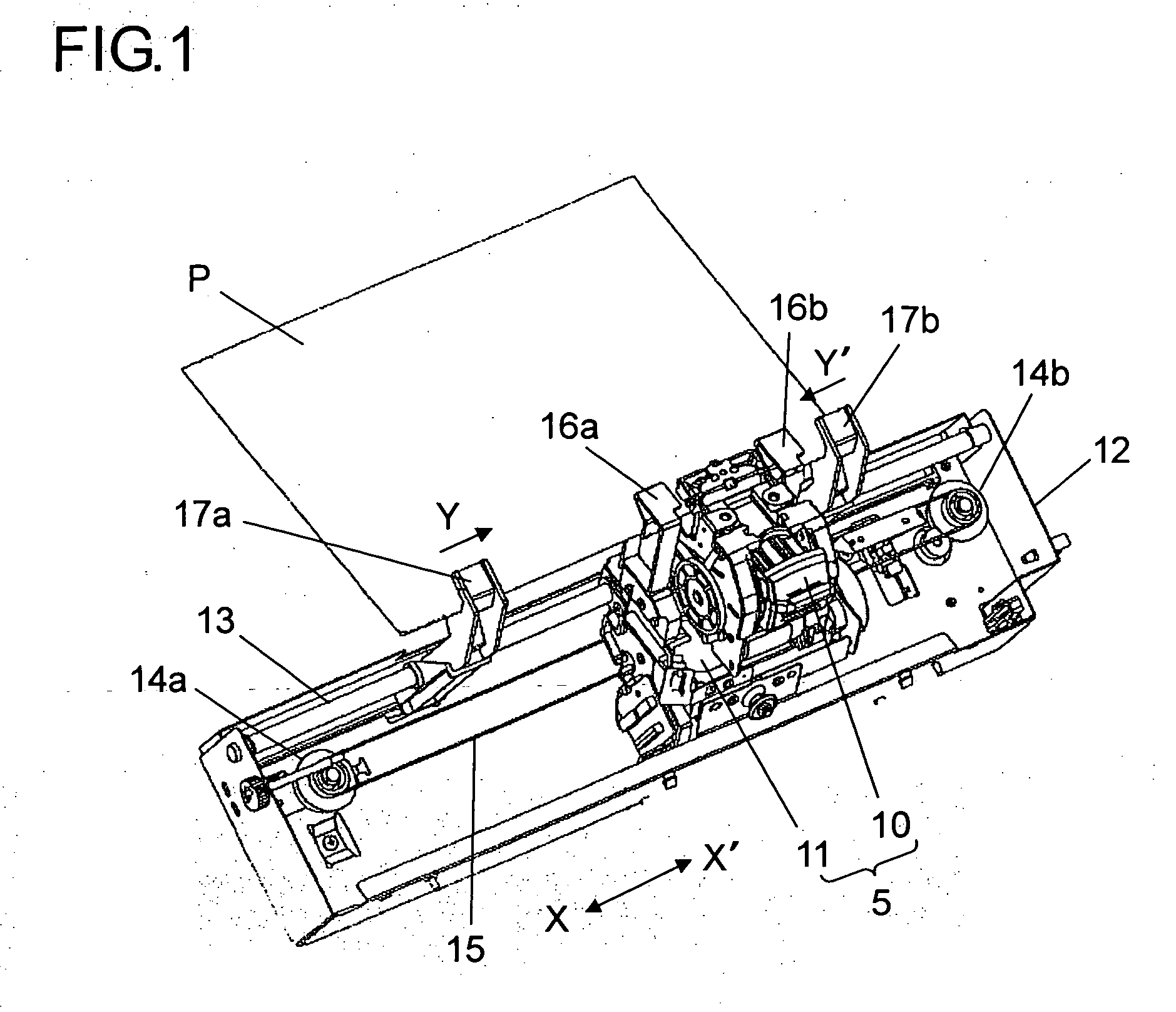
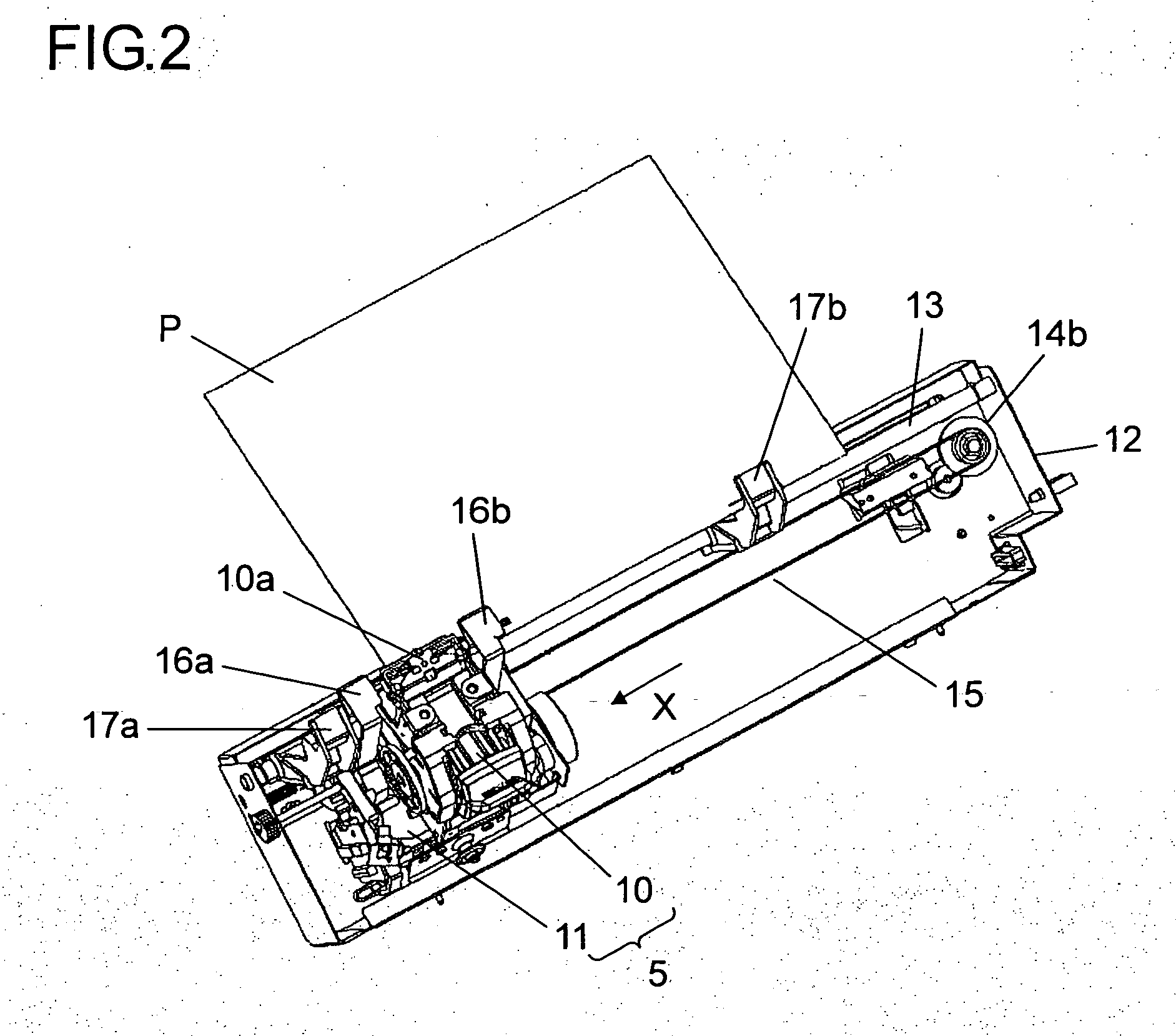
[0037] Hereinafter, embodiments of the present invention will be described with reference to the accompanying drawings. FIG. 1 is a perspective view showing the structure of the vicinity of the stapling unit of the paper post processing apparatus of a As shown in FIG. 1, a stapling unit 5 is so structured as to include a stapler 10 for performing stapling with respect to an edge of a stack of sheets of paper P stacked one on top of another in a processing tray 2 (see FIG. 10) and a carriage 11 on which the stapler 10 is mounted, and the carriage 11 is so formed as to be capable of shuttling along a guide axis 13 fitted in a frame 12 in directions (the directions indicated by arrows X-X′ in the figure) perpendicular to the paper transport direction. The carriage 11 is moved by driving a carriage motor (unillustrated) to rotate an endless belt 15 wound around and between pulleys 14a and 14b that transmit the driving power of the carriage motor to the endless belt 15.

[0038] On the car...

second embodiment

[0057] Next, a case will be described in which diagonal stapling is performed at one rear position of paper (hereinafter referred to as diagonal-one-rear-position stapling) by using the paper post processing apparatus of the Here, as in the case of one-rear-position stapling shown in FIG. 3, the stapling unit 5 is moved a predetermined amount in the direction indicated by arrow X′ until it meets the rear side end (right-hand side end in the figure) of the edge of the stack of sheets of paper P. Thereafter, by a stapler rotation motor (unillustrated), the stapler 10 is rotated a predetermined angular amount in the direction indicated by arrow R. At this time, the first stopper 16b is fixed to the body of the stapler 10 and hence rotates with the body of the stapler 10 in the direction indicated by arrow R.

[0058] With this structure, as in the first embodiment, by using the first stoppers 16a and 16b that are fixed to the stapling unit 5, in both cases of one-position stapling and tw...


PUM


Abstract

A stapling unit 5 includes a stapler 10 for stapling an edge part of a stack of sheets of paper P and a carriage 11 on which the stapler 10 is mounted, and the carriage 11 is formed in such a way that it can move along a guide axis 13 that is fitted in a frame 12 in a direction (X-X′ direction) perpendicular to the paper transport direction. On the carriage 11, a pair of first stoppers 16a and 16b that abut and thereby align the edge of the stack of sheets of paper P are fixed one at each side of the stapler 10 so as to be capable of shuttling in the directions indicated by arrows X and X′ together with the stapler 10. Outward of the first stoppers 16a and 16b, a pair of second stoppers 17a and 17b are further provided.

Description

[0001] This application is based on Japanese Patent Application No. 2005-315939 filed on Oct. 31, 2005, the contents of which are hereby incorporated by reference. BACKGROUND OF THE INVENTION [0002] 1. Field of the Invention [0003] The present invention relates to a paper post processing apparatus that performs sorting, stapling (binding), or the like with respect to sheets of paper that have undergone an image forming process. [0004] 2. Description of Related Art [0005] There are occasions where one wants to perform binding processing (hereinafter referred to as stapling) or hole-forming processing (hereinafter referred to as punching) with respect to a relatively large number of sheets of paper onto which images have been transferred by an image forming apparatus such as a copier or a printer. On such occasions, it is convenient to use a paper post processing apparatus, that is, a so-called finisher that automatically performs predetermined post processing such as stapling or punc...

Claims


Application Information

Patent Timeline
IPC IPC(8): B65H33/04
CPCB42C1/12B65H31/38B65H2408/1222
Inventor NISHIOKA, NOBUHIRO
Owner KYOCERA DOCUMENT SOLUTIONS INC
Why Eureka
Try Eureka