
Trolley

a trolley and wheel technology, applied in the field of trolleys, can solve the problems of increasing the environmental pollution of plastic bags, many problems and difficulties faced by consumers, and increasing the use of plastic bags as a major source of environmental pollution, so as to reduce the effect of loading and raising or lowering

Inactive Publication Date: 2007-05-03
WATSON MARK ANDREW
View PDF14 Cites 66 Cited by
  • Summary
  • Abstract
  • Description
  • Claims
  • Application Information

AI Technical Summary

Benefits of technology

[0019] Accordingly, the present invention provides an improved trolley or cart, preferably a shopping trolley, which can be used to support and transport a plurality of detachable bags or containers, and which can be raised or lowered for ease of loading and unloading of the plurality of detachable bags.
[0020] The trolley of the present invention is also preferably selectively adjustable to accommodate more or less bags or containers as r

Problems solved by technology

Many problems and difficulties have been encountered by consumers when employing such a conventional practice.
The action of placing shopping bags into a store shopping trolley, removing the bags from the trolley and placing them in a vehicle, and then removing the bags from the vehicle and lugging them inside can be a labour intensive exercise and an exercise of which some people are physically not capable of doing.
Aside from the problems that such a conventional practice presents to consumers, the use of plastic bags themselves is now considered a major source of environmental pollution.
To overcome the problems and difficulties of using such a conventional practice, so-called personal shopping trolleys have been developed, however, it is considered that none are very convenient.
However the use of this trolley still requires a consumer to unhook and lift the shopping bags from the trolley and into their vehicle and again from their vehicle and onto the trolley for transportation into their house.

Method used


Image

  • Trolley
  • Trolley
  • Trolley

Examples


Embodiment Construction

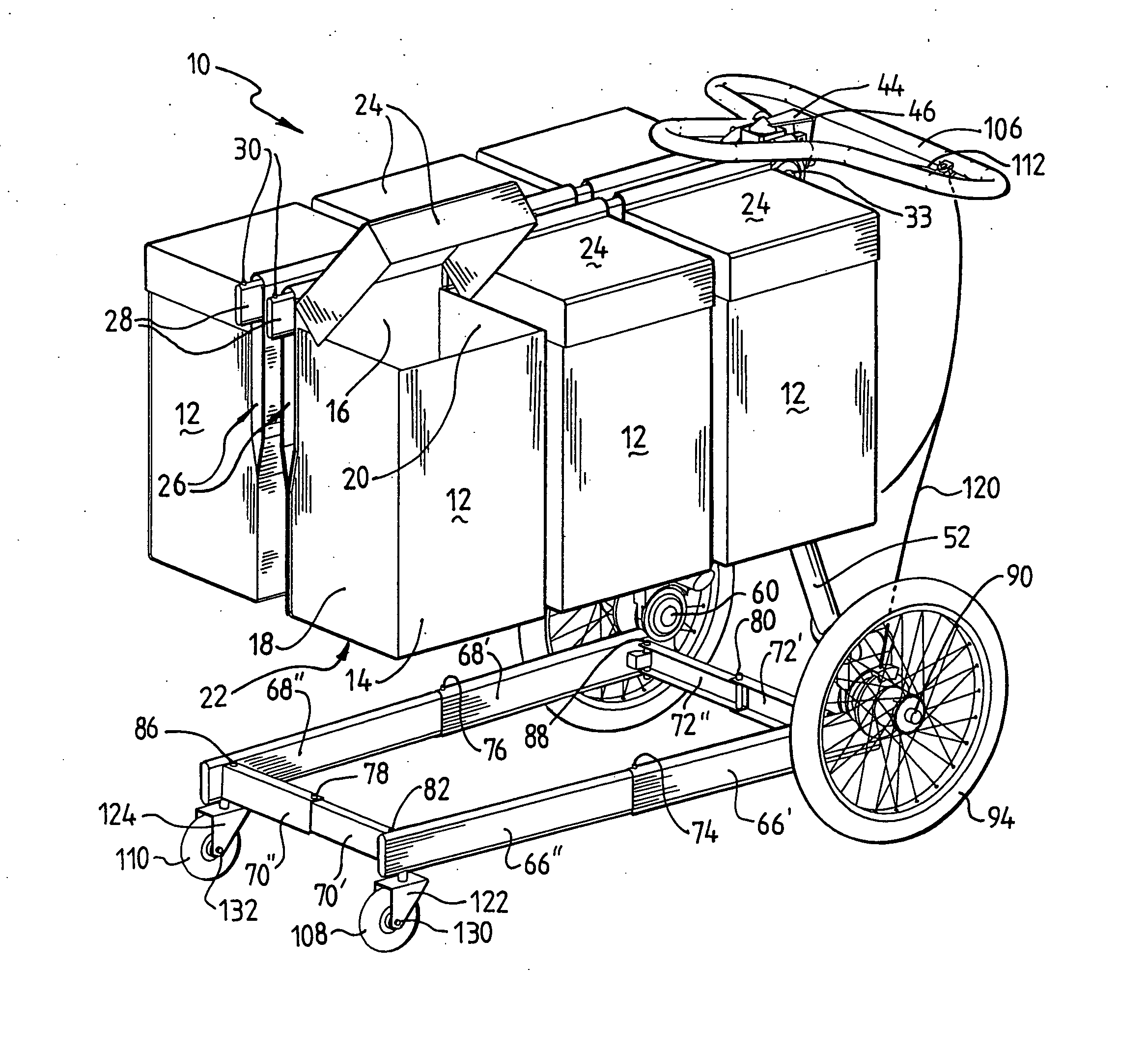
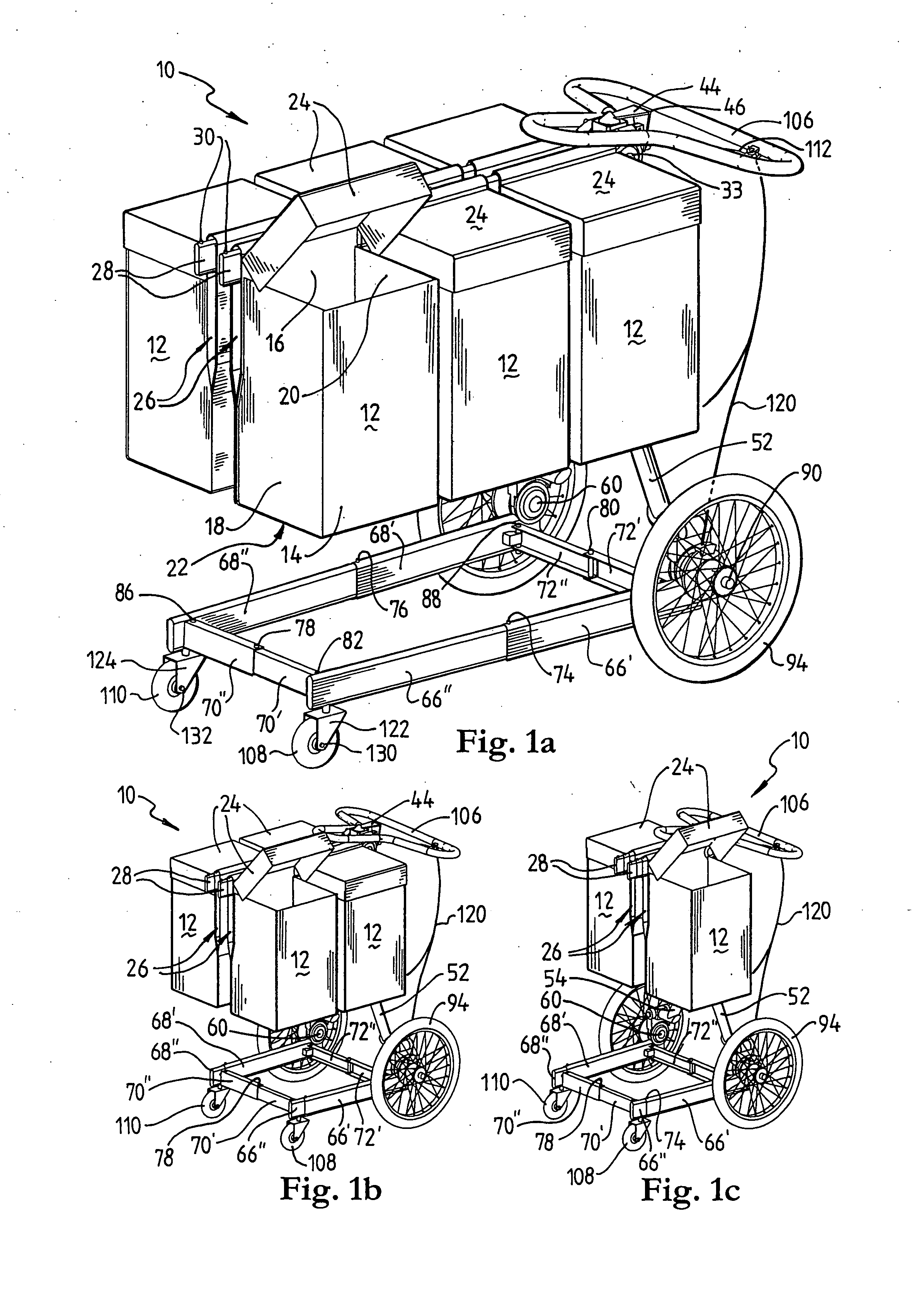
[0037] In FIGS. 1a to 1c there is shown a trolley or cart 10, suitable for use as a shopping trolley, designed to carry a plurality of detachable shopping bags or baskets 12. It should be understood however, that trolley 10 may be used for many other applications and as such the invention is not limited to the specific example as shown.

[0038] As can be best seen in FIGS. 1a &3, detachable bags 12 each have a generally rigid box-like design with front and rear sides 14,16, left and right sides 18,20, a base 22 and a lid 24. Disposed on rear side 16 of each of bags 12 is a sleeve 26 for slidably receiving therein a substantially horizontal bag support member 28 of trolley 10. Sleeves 26 facilitate the attachment and removal of bags 12 relative to trolley 10. It should be understood that bags 12 may take many other forms to that shown in the accompanying representations and as such the invention is not limited to the specific example provided. Hence, throughout the ensuing description...


PUM


Abstract

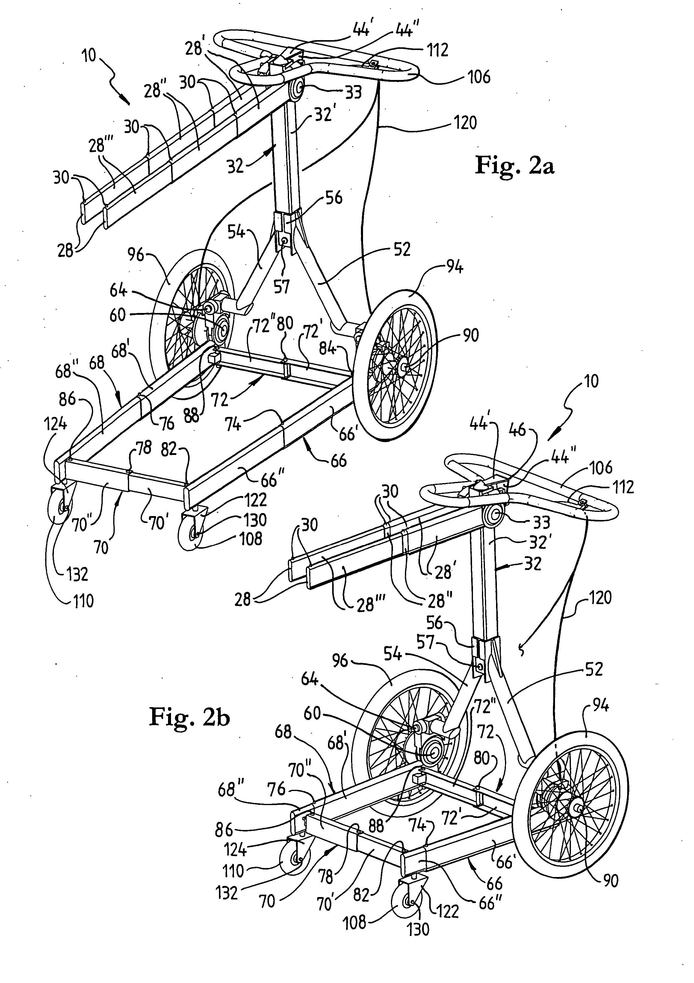
A trolley or cart (10) for supporting and transporting a plurality of bags or containers (12). The trolley (10) including a frame having a base section (52,54,66,68,70,72) and at least one stanchion (32) coupled to the base section (52,54,66,68,70,72). The at least one stanchion (32) including at least two telescoping sections (32′,32″) coupled together in a slidable relationship. A height adjustment means (34) is associated with the at least one stanchion (32) which enables the length of the at least one stanchion (32) to be selectively adjusted by raising and lowering an upper telescoping section (32′) relative to a lower telescoping section (32″). Wheel means (94,96,108,110) are rotatably coupled to the base section (52,54,66,68,70,72) of the frame and at least one handle member (106) is coupled to the upper telescoping section (32″) of the at least one stanchion (32) for selectively manipulating the trolley (10). The trolley (10) further including at least one support member (28) coupled to and extending substantially laterally from the at least one stanchion (32) at or near the upper telescoping section (32′) of the at least one stanchion (32) in a load supporting position. The at least one support member (28) being adapted to receive and support the plurality of bags or containers (12).

Description

FIELD OF THE INVENTION [0001] The present invention relates, generally, to wheeled trolleys or carts and relates particularly, though not exclusively, to a trolley for supporting and transporting a plurality of bags or containers. More particularly, the present invention relates to a shopping trolley for supporting and transporting a plurality of detachable shopping bags or containers and which includes a collapsible frame for loading into a motor vehicle. [0002] It will be convenient to hereinafter describe the invention in relation to a shopping trolley, however it should be appreciated that the trolley of the present invention is not limited to that use only. BACKGROUND OF THE INVENTION [0003] Any discussion of documents, devices, acts or knowledge in this specification is included to explain the context of the invention. It should not be taken as an admission that any of the material forms a part of the prior art base or the common general knowledge in the relevant art in Austra...

Claims


Application Information

Patent Timeline
IPC IPC(8): B62B3/02
CPCB62B3/027B62B3/106B62B5/0003B62B5/04B62B2005/0471B62B2203/10B62B2206/06B62B5/0438
Inventor WATSON, MARK ANDREW
Owner WATSON MARK ANDREW
Learn More