
Bottom-loading cooking appliance

a cooking appliance and bottom-loading technology, applied in the field of kitchen appliances, can solve the problems of people with limited mobility, limited reach or ability, and particular problems, and achieve the effect of mitigating the disadvantages of known cooking appliances and ovens

Inactive Publication Date: 2016-12-06
MARTIN JOHN PALMER
View PDF8 Cites 3 Cited by
  • Summary
  • Abstract
  • Description
  • Claims
  • Application Information

AI Technical Summary

Benefits of technology

Enables independent cooking for individuals with physical challenges by reducing the need for lifting and providing accessible controls, enhancing safety and convenience through the use of a low-profile drive mechanism and sensors.

Problems solved by technology

This type of arrangement poses a number of problems to people with limited mobility, including those who use a wheelchair, or those that have limited reach or ability to lift items in and out of a conventional cabinet or kitchen appliance which is above or below the countertop level.
However, in most existing homes and kitchens, use of a conventional oven, e.g. for baking or roasting, requires lifting and handling of larger hot and / or heavy dishes.
This poses particular problems.
However, with limited grip and strength to be able to lift dishes off the countertop into the oven and back again, assistance from another person is required to lift dishes in order to use a conventional oven, or even a countertop microwave oven.
Clearly, this can be very frustrating and limits a person's independence, as well as menu choices.
Even for able bodied users, such designs pose problems for cleaning and maintenance, e.g., is difficult to reach inside the oven for cleaning.

Method used


Image

  • Bottom-loading cooking appliance
  • Bottom-loading cooking appliance
  • Bottom-loading cooking appliance

Examples


Embodiment Construction

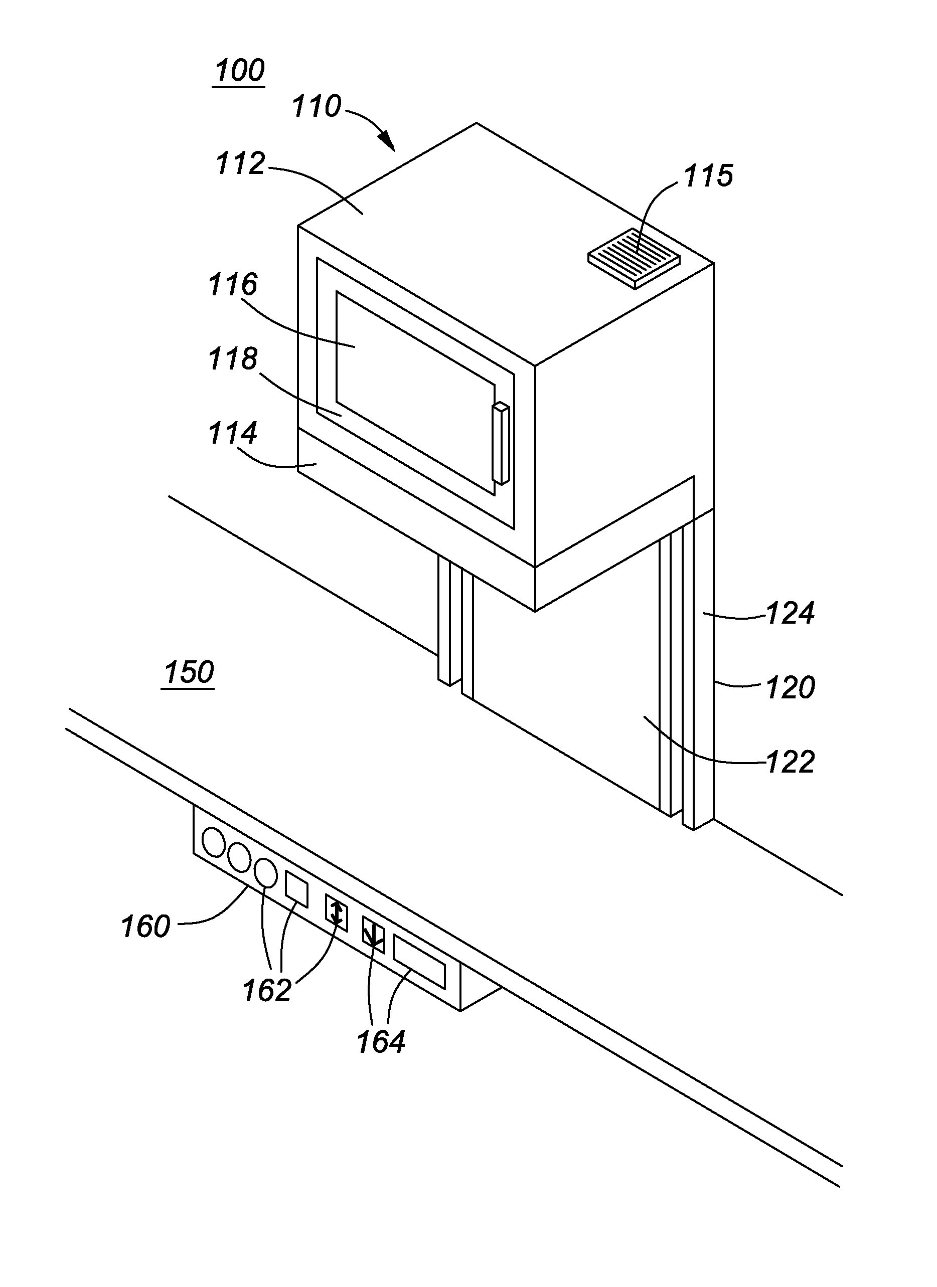
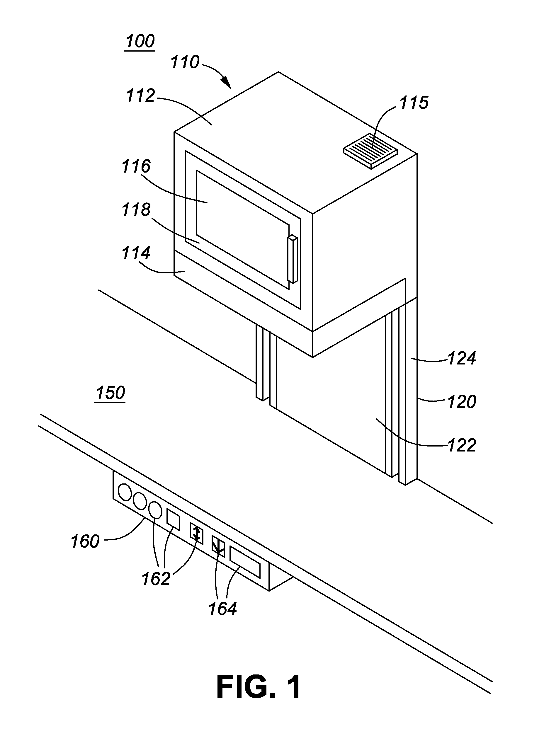
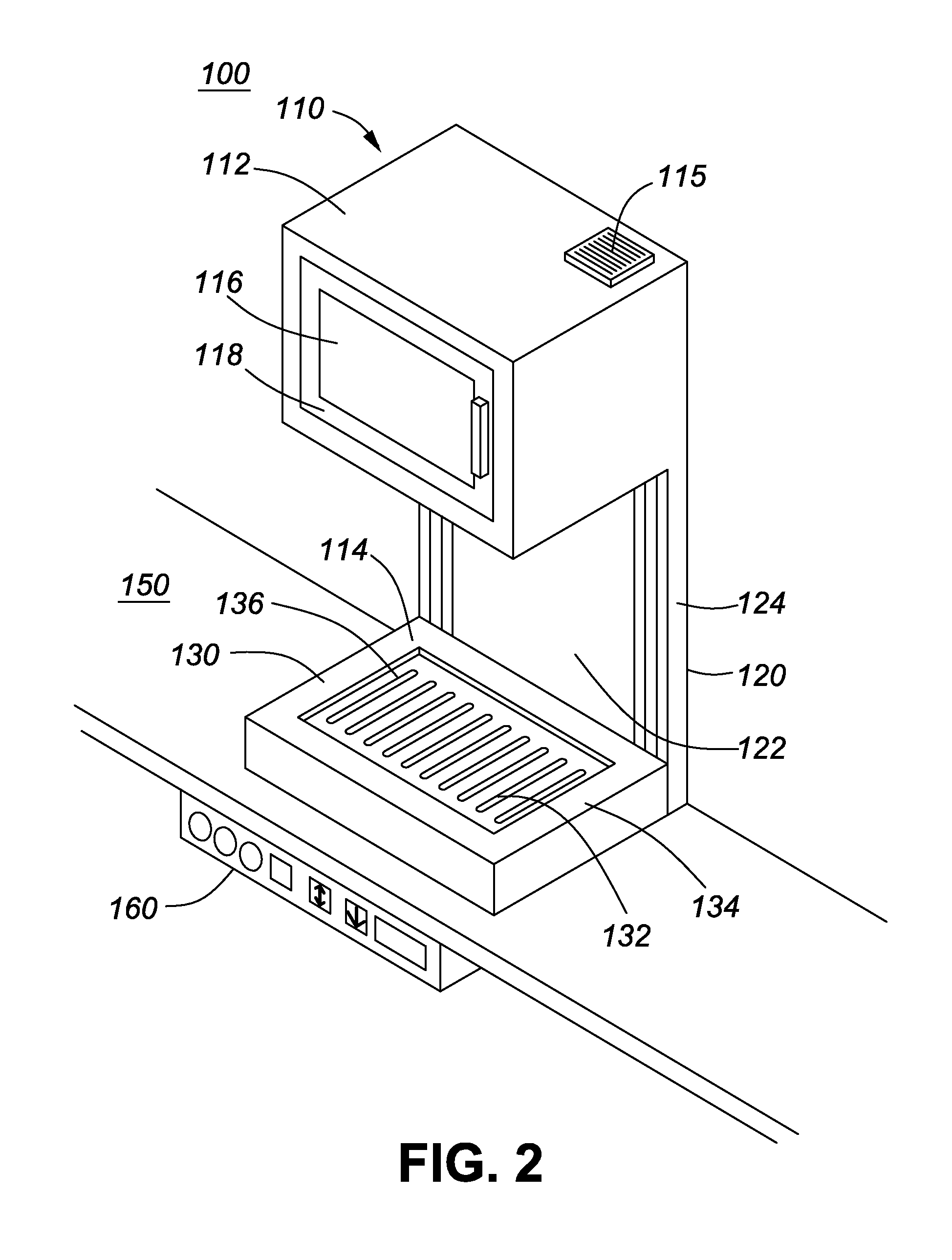
[0033]FIG. 1 illustrates a cooking appliance 100 comprising a wall-mounted unit 110, comprising a cooking chamber 112, i.e. an oven, having a bottom-opening door 114 mounted above a work area on a countertop 150. The door 114 is raised and lowered by a drive system 120, comprising guide rails 124 extending against the wall beneath the oven. A cover plate 122 hides the lift / drive mechanism, which is shown in more detail in FIGS. 3 to 8.

[0034]The door 114 is cantilevered from a support bar (not visible in this Figure) that extends between guide rails 124 on each side of the housing 122. The appliance is shown in FIG. 1 with the door closed, i.e. the door / platform 114 is raised. The drive system 120 for raising and lowering the door is low profile against the wall to leave the workspace free on the countertop underneath the oven unit 110. Controls 162 are provided by a separate unit, i.e. a remote control panel 160 that is mounted just below the countertop 150. The control panel provid...


PUM


Abstract

A cooking appliance is disclosed, comprising a wall-mounted cooking chamber, i.e. oven, with a bottom-opening door and separate countertop control panel, which facilitates use by individuals with disabilities, injuries or limited mobility, such as wheelchair users. The oven is wall-mounted, at a convenient distance, above a kitchen countertop, leaving a useful area of countertop underneath. Advantageously, it includes a low profile motor driven lift mechanism, housed against the wall beneath the oven and comprising guide rails for lowering the door to counter level and raising it to the closed, cooking position. The door provides a platform for items to be cooked. When lowered to counter level, a user can slide dishes between the platform and the adjacent countertop, without need for lifting as in a conventional stove or wall-mounted oven. An easy to reach, counter-level control unit enables the user to control oven functions including raising / lowering the door.

Description

CROSS-REFERENCE TO RELATED APPLICATION[0001]This application claims priority from U.S. Provisional Patent Application No. 61 / 771,395, filed Mar. 1, 2013, entitled “Bottom Loading Cooking Appliance”, which is incorporated herein by reference in its entirety.TECHNICAL FIELD[0002]This invention relates to kitchen appliances, and particularly to domestic cooking appliances comprising an oven, e.g. for baking and roasting, and also relates to kitchen appliances that facilitate use by individuals with disabilities or physical constraints.BACKGROUND[0003]Conventional kitchen designs are arranged with kitchen appliances including a stove or oven, and countertops of a standard height, typically with storage units under the countertops and wall storage cabinets above. This type of arrangement poses a number of problems to people with limited mobility, including those who use a wheelchair, or those that have limited reach or ability to lift items in and out of a conventional cabinet or kitchen...

Claims


Application Information

Patent Timeline
Patent Type & Authority Patents(United States)
IPC IPC(8): F24C15/02
CPCF24C15/027
Inventor MARTIN, JOHN PALMER
Owner MARTIN JOHN PALMER
Learn More