
Nacelle component for a wind turbine and method for mounting a nacelle component

a technology for wind turbines and components, which is applied in the direction of wind turbines, wind motor assemblies, wind turbines, etc., can solve the problems of increasing complexity in transportation and erecting wind turbines, and reducing the complexity of erecting wind turbines. the effect of complexity

Active Publication Date: 2020-09-22
SIEMENS GAMESA RENEWABLE ENERGY SERVICE GMBH
View PDF18 Cites 1 Cited by
  • Summary
  • Abstract
  • Description
  • Claims
  • Application Information

AI Technical Summary

Benefits of technology

[0004]An object of the invention is to provide a nacelle component and a method for mounting a nacelle component, by means of which both the complexity of transportation and also the complexity when erecting the wind turbine can be minimized.
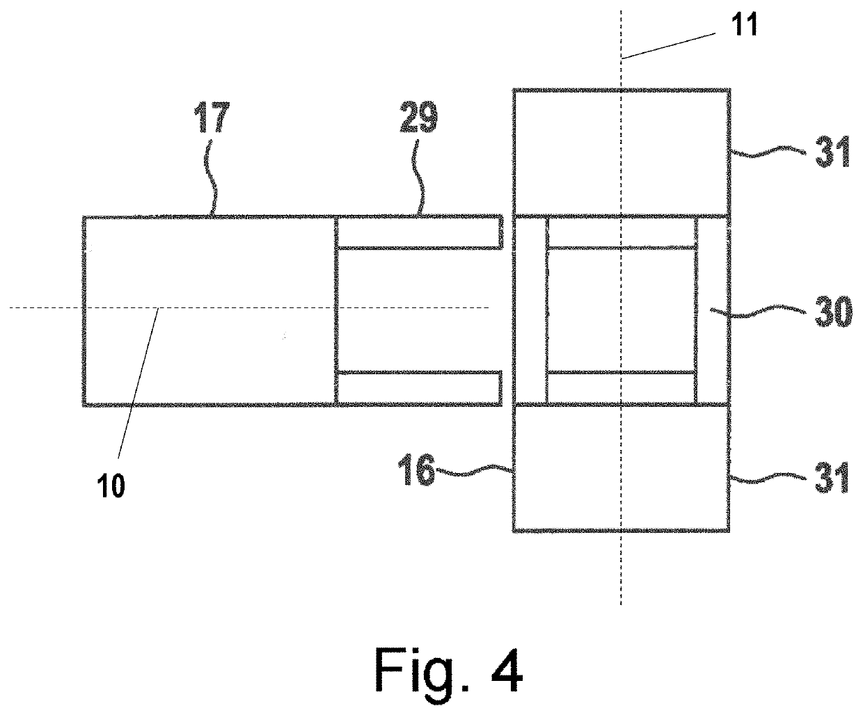
[0006]The available space can be used effectively by the two modules being arranged in the nacelle component with different orientations, as a result of which the nacelle can be assembled from a reduced number of modules. The dimensions of the modules are nevertheless still such that they can be readily transported. A favorable load distribution can moreover be achieved owing to the transversely arranged power electronics module because the components arranged on the power electronics module have a reduced distance from the axis of rotation of the nacelle. The load torque can consequently be reduced.
[0026]The power electronics module may be placed in a pre-mounted state by virtue of the component carrier being connected to the frame part and by virtue of one or more components of the power electronics module being connected to the component carrier. Alternatively, the component carrier may also be connected to the frame part of the power electronics module, or separated again from the frame part of the power electronics module, at any desired later stage of the assembly process. The component carrier may be configured such that, when equipped with the elements, held by the component carrier, of the power electronics module, said component carrier can be moved using a lifting apparatus; for this purpose, the component carrier may have lifting devices, for example in the form of eyelets, diverting rollers and / or winches. Alternatively or in addition, the component carrier may be designed to be lifted using a lifting platform; for this purpose, the component carrier may for example have a flat underside for stable support on the lifting platform and / or may, at the edges, be compatible with container corners or twist locks, whereby a firm connection to a suitable lifting platform is made possible. The component carrier according to the invention facilitates the maneuvering of elements of the power electronics module between the nacelle installed on the tower and the ground, whereby an exchange of components or repair of components on the ground are facilitated.
[0031]The system may have an auxiliary lifting apparatus, wherein the auxiliary lifting apparatus may be designed for the raising and lowering of relatively small loads between the nacelle component installed on the tower and the ground. A relatively small load may for example be the cables of the winches of the lifting platform. The auxiliary lifting apparatus may for example be an on-board crane or a winch. The mainframe module or preferably the power electronics module may comprise a mounting for the auxiliary lifting apparatus. The mainframe module or the power electronics module may be placed in a pre-mounted state by virtue of the auxiliary lifting apparatus being connected to the mainframe module or to the power electronics module. As an example for the use of the system, the lowering of a component out of the nacelle of the wind turbine is described in each case. Correspondingly, the system can be utilized in order to raise a component from the ground to the nacelle and install said component there. The invention furthermore relates to corresponding methods for lowering a component out of the nacelle of a wind turbine and for raising a component to the nacelle of a wind turbine. The power electronics module and / or the mainframe module may comprise housings, wherein the housings protect the components of the power electronics module and / or of the mainframe module for example against environmental influences. The housing of the power electronics module may be self-supporting. This may mean in particular that a lateral housing part extends between an upper end and a lower end without being supported over the area by a skeletal frame. Frame struts of the power electronics module may extend along the upper, lower and / or lateral ends of the housing part. Along its edges, the housing part may be connected to the frame struts. The self-supporting design saves space and weight. A power electronics module having a housing of said type has independent inventive substance even if the power electronics module is not used in the context of a nacelle component according to the invention.
[0053]Each transport unit may have one or more lifting points. The articulation points may be arranged so as to enclose the center of gravity of the transport unit between them, such that stable lifting of the transport unit is possible.

Problems solved by technology

As output increases, the components of wind turbines become larger and heavier, as a result of which the complexity in terms of transportation and erecting wind turbines rises.
The individual modules can be transported from the manufacturing plant to the site where the wind turbine is erected with a manageable degree of complexity.
However, there is a certain degree of complexity involved in erecting the wind turbine when the nacelle has to be assembled from a relatively large number of modules.

Method used


Image

  • Nacelle component for a wind turbine and method for mounting a nacelle component
  • Nacelle component for a wind turbine and method for mounting a nacelle component
  • Nacelle component for a wind turbine and method for mounting a nacelle component

Examples


Embodiment Construction

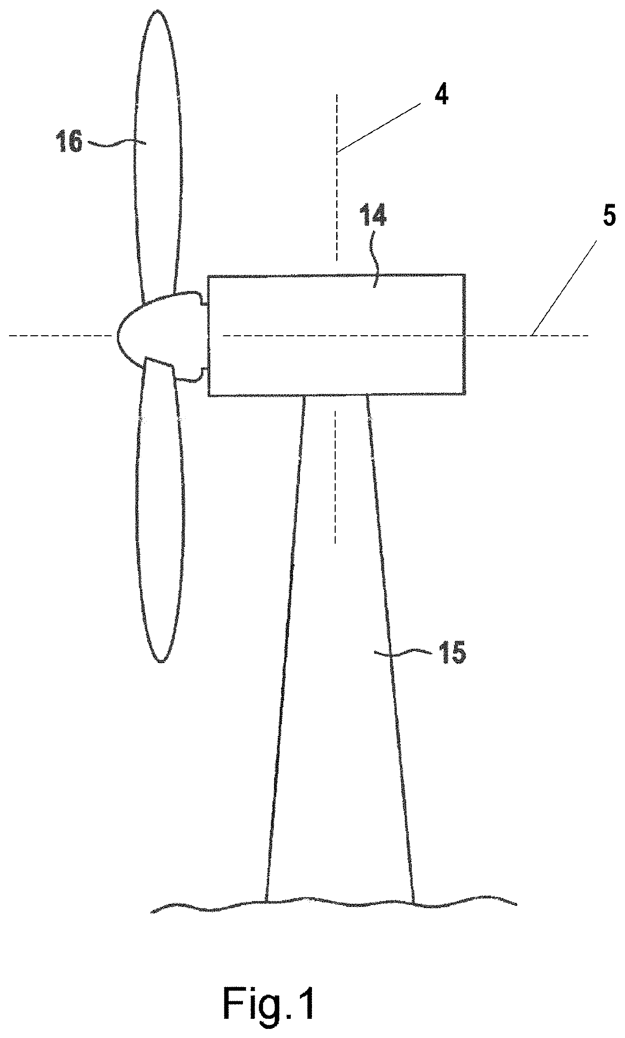
[0066]In a wind turbine according to aspects of the disclosure shown in FIG. 1, a nacelle 14 is mounted on a tower 15 to rotate about a nacelle axis of rotation 4. A rotor 6 is set in rotation about a rotational axis 5 by the wind and drives a generator 23 via a gearbox 22. The generator 23 generates electricity which is fed into a power grid via a converter 24 and a transformer 25.

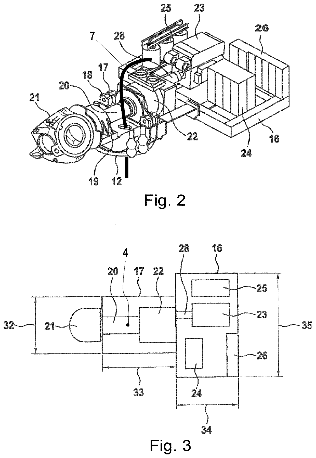
[0067]A nacelle component shown in FIG. 2, which comprises a power electronics module 16 and a mainframe module 17, is arranged inside the nacelle 14. The mainframe module 17 comprises bearing blocks 18, 19 via which a rotor shaft 20 is rotatably mounted. A rotor hub 21 is connected to the front end of the rotor shaft 20. The rear end of the rotor shaft 20 is connected to the low-speed shaft of the gearbox 22. The mainframe module 17 comprises a slewing ring 12 via which the nacelle 14 is mounted so that it can rotate relative to the tower 15.

[0068]The power electronics module 16 carries a generator 23, a...


PUM


Abstract

A nacelle component for a nacelle of a wind turbine, comprising a mainframe module and a power electronics module. The mainframe module and the power electronics module in each case have a length greater than a width. In the assembled state of the nacelle component, the mainframe module is oriented with its longitudinal axis parallel to a vertical plane which extends through the axis of a rotor shaft. The longitudinal axis of the power electronics module intersects the vertical plane which extends through the axis of the rotor shaft. A method for mounting such a nacelle component is also disclosed.

Description

BACKGROUND[0001]The disclosure relates to a nacelle component for a wind turbine, and a method for mounting a nacelle component.[0002]In wind turbines, a nacelle is usually arranged rotatably on a tower. The nacelle carries a rotor which is connected to a generator via a rotor shaft. The rotor is set in rotation by the wind and drives the generator such that electrical energy is generated. The rotor can be oriented in the direction of the wind by rotating the nacelle relative to the tower.[0003]As output increases, the components of wind turbines become larger and heavier, as a result of which the complexity in terms of transportation and erecting wind turbines rises. It is known from WO 2016 / 116112 A1, EP 2 573 387 A1 for a nacelle to be composed of a plurality of modules. The individual modules can be transported from the manufacturing plant to the site where the wind turbine is erected with a manageable degree of complexity. However, there is a certain degree of complexity involv...

Claims


Application Information

Patent Timeline
Patent Type & Authority Patents(United States)
IPC IPC(8): F03D80/80F03D9/25F03D80/00F03D13/10F03D13/20F03D80/50
CPCF03D9/25F03D80/50F03D13/10F03D80/00F03D13/20F03D80/80F03D80/85F05B2240/916F05B2240/14F03D80/82Y02E10/72Y02E10/728
Inventor TREDE, ALF
Owner SIEMENS GAMESA RENEWABLE ENERGY SERVICE GMBH
Learn More